METER / GAUGE SYSTEM Meter Illumination does not Dim at Night
DESCRIPTION
In this circuit, the combination meter assembly receives auto dimmer signals from the main body ECU (multiplex network body ECU) via CAN communication. When the combination meter assembly receives an auto dimmer signal, it dims the meter illumination (warning and indicator lights).
The main body ECU (multiplex network body ECU) determines whether it is daytime or nighttime based on the waveform transmitted from the automatic light control sensor. If the main body ECU (multiplex network body ECU) determines that it is nighttime and the headlight dimmer switch assembly is in the tail, head, or AUTO position, the ECU sends an auto dimmer signal to the combination meter assembly.
According to this signal, the combination meter assembly dims the meter illumination.
Tech Tips
When the meter illumination does not dim at night, there may be a malfunction in the automatic light control sensor, main body ECU (multiplex network body ECU), CAN communication system, wire harness, connector, or combination meter assembly.
WIRING DIAGRAM
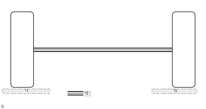
| *1 | Main Body ECU (Multiplex Network Body ECU) |
| *2 | CAN Communication Line |
| *3 | Combination Meter Assembly |
CAUTION / NOTICE / HINT
Note
-
Before replacing the main body ECU (multiplex network body ECU), refer to Service Bulletin.
-
When replacing the combination meter assembly, always replace it with a new one. If a combination meter assembly which was installed to another vehicle is used, the information stored in it will not match the information from the vehicle and a DTC may be stored.
Tech Tips
-
The automatic light control sensor sensitivity can be customized.
-
Setting the meter illumination level to maximum brightness prevents the meter illumination from dimming when the headlight dimmer switch assembly is changed to the tail, head, or AUTO position at night. Therefore, check the meter illumination setting before proceeding to the following steps.
PROCEDURE
-
CHECK CAN COMMUNICATION SYSTEM
-
Check if CAN communication DTCs are output.
Result Result Proceed to CAN communication DTCs are not output. A CAN communication DTCs are output. B
B 
GO TO CAN COMMUNICATION SYSTEM Click here
A 
-
-
CHECK FOR DTC
-
Check if lighting system DTCs are output.
Body Electrical > Main Body > Trouble CodesResult Result Proceed to DTC B1244 is not output. A DTC B1244 is output. B
B
GO TO DTC B1244 Click here
A
-
-
CHECK COMBINATION METER ASSEMBLY
-
Replace the combination meter assembly with a new one.
-
Check the operation.
OK The operation of the combination meter assembly returns to normal. Result Proceed to OK NG
OK
END (COMBINATION METER ASSEMBLY IS DEFECTIVE)
NG
REPLACE MAIN BODY ECU (MULTIPLEX NETWORK BODY ECU) Click here
-