WATER PUMP INSTALLATION
PROCEDURE
-
INSTALL ENGINE WATER PUMP ASSEMBLY
-
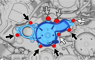

Bolt A 
Bolt B 
Bolt C Install a new water pump gasket and the engine water pump assembly to the timing chain cover assembly with the 9 bolts.
- Torque:
- for bolt A
- 20 N*m { 204 kgf*cm, 15 ft.*lbf }
- for bolt B
- 23 N*m { 235 kgf*cm, 17 ft.*lbf }
- for bolt C
- 47 N*m { 479 kgf*cm, 35 ft.*lbf }
Bolt Length Item Length Bolt A 25 mm (0.984 in.) Bolt B 70 mm (2.76 in.) Bolt C 80 mm (3.15 in.)
-
-
INSTALL WATER PUMP PULLEY
-
Temporarily install the water pump pulley with the 4 bolts.
-
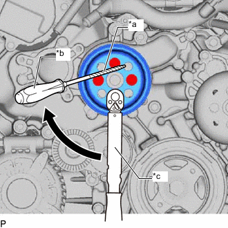
*a Protective Tape *b Hold *c Turn Using a screwdriver or equivalent with its tip wrapped in protective tape, hold the water pump pulley and tighten the 4 bolts.
- Torque:
- 21 N*m { 214 kgf*cm, 15 ft.*lbf }
-
-
INSTALL WATER INLET HOUSING
-
Install the water inlet housing to the No. 3 water by-pass hose, and slide the clip to secure the hose.
-
Install the water inlet hose to the water inlet housing and front water by-pass joint and, slide the 2 clips to secure the hose.
-
Install a new No. 1 water inlet housing gasket to the engine water pump assembly.
-
Install the water inlet housing to the engine water pump assembly with the 3 bolts.
- Torque:
- 21 N*m { 214 kgf*cm, 15 ft.*lbf }
Note
Be careful not to allow the No. 1 water inlet housing gasket to get caught between the parts.
-
Connect the No. 5 water by-pass hose to the water inlet housing, and slide the clip to secure the hose.
-
Install the wire harness clamp bracket to the water inlet housing with the bolt.
- Torque:
- 12 N*m { 122 kgf*cm, 9 ft.*lbf }
-
-
CONNECT NO. 3 RADIATOR HOSE
-
INSTALL FAN AND GENERATOR V BELT
-
CONNECT RESERVE TANK OUTLET HOSE
-
Connect the reserve tank outlet hose to the water inlet housing, and slide the clip to secure the hose.
-
-
INSTALL INTAKE AIR CONNECTOR PIPE
-
INSTALL AIR CLEANER HOSE ASSEMBLY
-
CONNECT NO. 3 PCV HOSE
-
CONNECT NO. 2 PCV HOSE
-
INSTALL AIR CLEANER WITH ELEMENT ASSEMBLY RH
-
INSTALL AIR CLEANER WITH ELEMENT ASSEMBLY LH
-
INSTALL RADIATOR SUPPORT TO CROSSMEMBER BRACE SUB-ASSEMBLY RH
-
INSTALL RADIATOR SUPPORT TO CROSSMEMBER BRACE SUB-ASSEMBLY LH
-
ADD ENGINE COOLANT
-
INSPECT FOR COOLANT LEAK
-
INSTALL ENGINE UNDER COVER REINFORCEMENT
-
INSTALL NO. 1 ENGINE UNDER COVER ASSEMBLY
-
INSTALL LOWER RADIATOR AIR DEFLECTOR
-
INSTALL RADIATOR SUPPORT TO FRAME SEAL RH
-
INSTALL RADIATOR SUPPORT TO FRAME SEAL LH
-
INSTALL V-BANK COVER SUB-ASSEMBLY