CAN COMMUNICATION SYSTEM, Diagnostic DTC:U0129
| DTC Code | DTC Name |
|---|---|
| U0129 | Lost Communication with Skid Control ECU |
DESCRIPTION
| DTC No. | Detection Item | DTC Detection Condition | Trouble Area | DTC Output from |
|---|---|---|---|---|
| U0129 | Lost Communication with Skid Control ECU | Communication stop occurs between the skid control ECU assembly and ECU or sensor outputs DTC(s) |
|
|
WIRING DIAGRAM
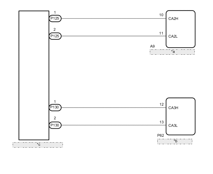
| *a | Skid Control ECU Assembly |
| *b | Driving Support ECU Assembly |
| *c | No. 8 CAN Junction Connector |
CAUTION / NOTICE / HINT
CAUTION:
When performing the confirmation driving pattern, obey all speed limits and traffic laws.
Note
-
Because the order of diagnosis is important to allow correct diagnosis, make sure to begin troubleshooting using How to Proceed with Troubleshooting when CAN communication system related DTCs are output.
-
Before measuring the resistance of the CAN bus, turn the engine switch off and leave the vehicle for 1 minute or more without operating the key or any switches, or opening or closing the doors. After that, disconnect the cable from the negative (-) battery terminal and leave the vehicle for 1 minute or more before measuring the resistance.
-
After turning the engine switch off, waiting time may be required before disconnecting the cable from the negative (-) battery terminal. Therefore, make sure to read the disconnecting the cable from the negative (-) battery terminal notices before proceeding with work.
-
Some parts must be initialized and set when replacing or removing and installing parts.
-
After performing repairs, perform the DTC check procedure and confirm that the DTCs are not output again.
DTC check procedure: Turn the engine switch on (IG) and wait for 1 minute or more. Then operate the suspected malfunctioning system and drive the vehicle at 60 km/h (37 mph) or more for 5 minutes or more.
-
After the repair, perform the CAN bus check and check that all the ECUs and sensors connected to the CAN communication system are displayed as normal.
Tech Tips
-
Before disconnecting related connectors for inspection, push in on each connector body to check that the connector is not loose or disconnected.
-
When a connector is disconnected, check that the terminals and connector body are not cracked, deformed or corroded.
PROCEDURE
-
CHECK FOR DTCs
-
Check for DTCs.
Result Result Proceed to DTC U0129 is output from driving support ECU assembly only. A DTC U0129 is output from any ECU. B
B 
CHECK FOR OPEN IN CAN BUS WIRE (SKID CONTROL ECU ASSEMBLY BRANCH WIRE) Click here
A 
-
-
CHECK FOR OPEN IN CAN BUS WIRE (DRIVING SUPPORT ECU ASSEMBLY BRANCH WIRE)
-
Disconnect the cable from the negative (-) battery terminal.
-
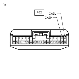
*a Front view of wire harness connector
(to Driving Support ECU Assembly)
Disconnect the driving support ECU assembly connector.
-
Measure the resistance according to the value(s) in the table below.
Standard Resistance Tester Connection Condition Specified Condition P62-12 (CA3H) - P62-13 (CA3L) Cable disconnected from negative (-) battery terminal 54 to 69 Ω Result Result OK NG
OK 
REPLACE DRIVING SUPPORT ECU ASSEMBLY Click here
NG
REPAIR OR REPLACE CAN BRANCH WIRE OR CONNECTOR
-
-
CHECK FOR OPEN IN CAN BUS WIRE (SKID CONTROL ECU ASSEMBLY BRANCH WIRE)
-
Disconnect the cable from the negative (-) battery terminal.
-
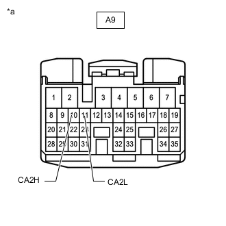
*a Front view of wire harness connector
(to Skid Control ECU Assembly)
Disconnect the skid control ECU assembly connector.
-
Measure the resistance according to the value(s) in the table below.
Standard Resistance Tester Connection Condition Specified Condition A9-10 (CA2H) - A9-11 (CA2L) Cable disconnected from negative (-) battery terminal 54 to 69 Ω Result Result OK NG
OK
REPLACE SKID CONTROL ECU ASSEMBLY for LHD: Click here
REPLACE SKID CONTROL ECU ASSEMBLY for RHD: Click hereNG
REPAIR OR REPLACE CAN BRANCH WIRE OR CONNECTOR
-