LIGHTING SYSTEM(w/o Automatic Headlight Beam Level Control System), Diagnostic DTC:B2430, B2431
| DTC Code | DTC Name |
|---|---|
| B2430 | LED Headlight LH |
| B2431 | LED Headlight RH |
DESCRIPTION
These DTCs are stored when the low beam headlights do not illuminate, or a communication malfunction is detected between the light control ECU and main body ECU (multiplex network body ECU).
Tech Tips
DTC B2430 or DTC B2431 may also be stored if a headlight cooling fan is malfunctioning. In this case, the light control ECU will dim or turn off the malfunctioning low beam headlight.
| DTC No. | Detection Item | DTC Detection Condition | Trouble Area | DTC Output from |
|---|---|---|---|---|
| B2430 | LED Headlight LH |
Detection condition:
Malfunction Status:
Malfunction Time: |
|
Main body ECU (multiplex network body ECU) |
| B2431 | LED Headlight RH |
Detection condition:
Malfunction Status:
Malfunction Time: |
|
Main body ECU (multiplex network body ECU) |
WIRING DIAGRAM
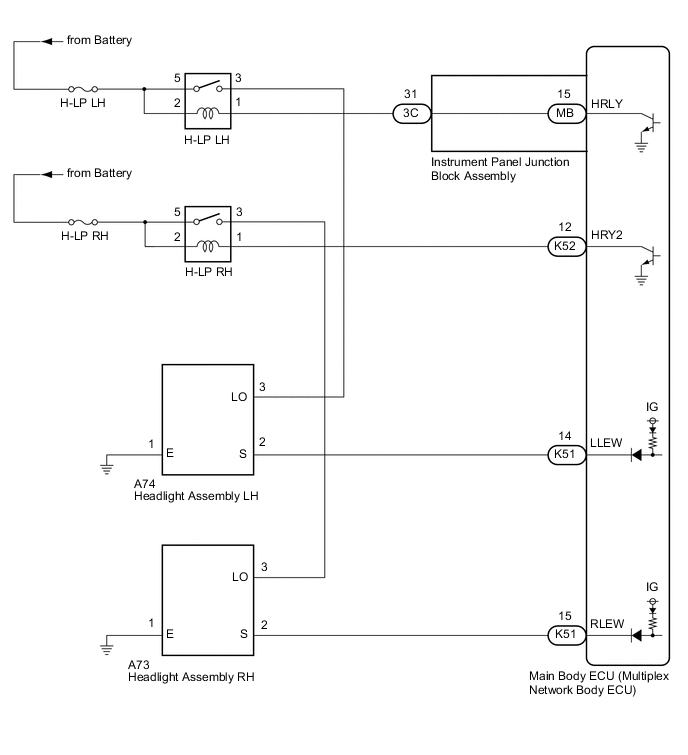
-
HEADLIGHT ASSEMBLY CIRCUIT
CAUTION / NOTICE / HINT
Note
-
Inspect the fuses for circuits related to this system before performing the following procedure.
-
Before replacing the main body ECU (multiplex network body ECU), refer to Service Bulletin.*
-
*: w/ Smart Entry and Start System
PROCEDURE
-
CLEAR DTC
-
Connect the GTS to the DLC3.
-
Turn the ignition switch to ON.
-
Turn the GTS on.
-
Enter the following menus: Body Electrical / Main Body / Trouble Codes.
-
Clear the DTCs.
Body Electrical > Main Body > Clear DTCsResult Proceed to NEXT
NEXT 
-
-
CHECK FOR DTC
-
Connect the GTS to the DLC3.
-
Start the engine.
-
Operate the light control switch to turn on the low beam headlights and wait 10 seconds or more.
-
Turn the GTS on.
-
Enter the following menus: Body Electrical / Main Body / Trouble Codes.
-
Check for DTCs.
Body Electrical > Main Body > Trouble CodesOK DTC B2430 and B2431 are not output. Result Result Proceed to OK A NG (DTC B2430 is output) B NG (DTC B2431 is output) C
A 
USE SIMULATION METHOD TO CHECK Click here
C 
INSPECT HEADLIGHT ASSEMBLY RH (LO TERMINAL VOLTAGE) Click here
B
-
-
INSPECT HEADLIGHT ASSEMBLY LH (LO TERMINAL VOLTAGE)
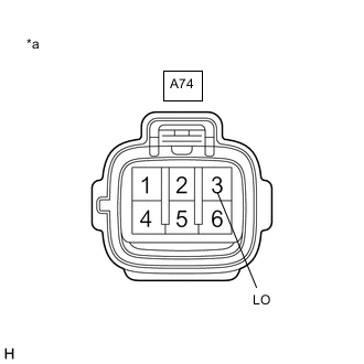
*a Front view of wire harness connector
(to Headlight Assembly LH)
-
Disconnect the A74 headlight assembly LH connector.
-
Measure the voltage according to the value(s) in the table below.
Standard Voltage Tester Connection Condition Specified Condition A74-3 (LO) - Body ground Light control switch in head position 11 to 14 V Result Proceed to OK NG
NG
CHECK HARNESS AND CONNECTOR (H-LP LH RELAY - HEADLIGHT ASSEMBLY LH) Click here
OK
-
-
CHECK HARNESS AND CONNECTOR (HEADLIGHT ASSEMBLY LH - BODY GROUND)
-
Measure the resistance according to the value(s) in the table below.
Standard Resistance Tester Connection Condition Specified Condition A74-1 (E) - Body ground Always Below 1 Ω Result Proceed to OK NG
NG
REPAIR OR REPLACE HARNESS OR CONNECTOR
OK
-
-
INSPECT HEADLIGHT ASSEMBLY LH (S TERMINAL VOLTAGE)

*a Front view of wire harness connector
(to Headlight Assembly LH)
-
Measure the voltage according to the value(s) in the table below.
Standard Voltage Tester Connection Condition Specified Condition A74-2 (S) - Body ground Ignition switch ON 11 to 14 V Result Proceed to OK NG
NG
CHECK HARNESS AND CONNECTOR (HEADLIGHT ASSEMBLY LH - MAIN BODY ECU (MULTIPLEX NETWORK BODY ECU)) Click here
OK
-
-
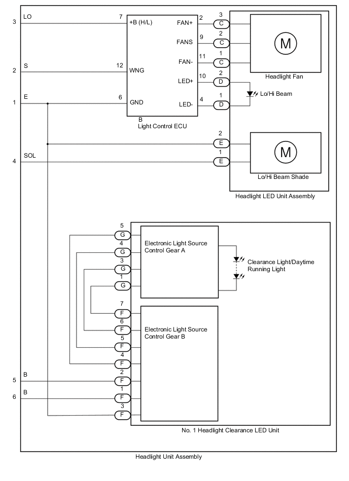
INSPECT HEADLIGHT UNIT ASSEMBLY LH
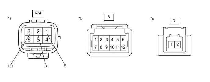
*a Component without harness connected
(to Wire Harness)
*b Component without harness connected
(to Light Control ECU)
*c Component without harness connected
(to Headlight LED Unit Assembly LH)
- -
-
Remove the headlight assembly LH.
-
Remove the headlight unit assembly LH.
-
Measure the resistance according to the value(s) in the table below.
Standard Resistance Tester Connection Condition Specified Condition A74-1 (E) - B-6 Always Below 1 Ω A74-2 (S) - B-12 Always Below 1 Ω A74-3 (LO) - B-7 Always Below 1 Ω B-4 - D-1 Always Below 1 Ω B-10 - D-2 Always Below 1 Ω Result Proceed to OK NG
NG
REPLACE HEADLIGHT UNIT ASSEMBLY LH Click here
OK
-
-
CHECK LIGHT CONTROL ECU
-
Remove each light control ECU, interchange the light control ECU (for LH) with (for RH) and connect the connectors.
Result Proceed to NEXT
NEXT
-
-
CLEAR DTC
-
Connect the GTS to the DLC3.
-
Turn the ignition switch to ON.
-
Turn the GTS on.
-
Enter the following menus: Body Electrical / Main Body / Trouble Codes.
-
Clear the DTCs.
Body Electrical > Main Body > Clear DTCsResult Proceed to NEXT
NEXT
-
-
CHECK FOR DTC
-
Connect the GTS to the DLC3.
-
Start the engine.
-
Operate the light control switch to turn on the low beam headlights and wait 10 seconds or more.
-
Turn the GTS on.
-
Enter the following menus: Body Electrical / Main Body / Trouble Codes.
-
Check for DTCs.
Body Electrical > Main Body > Trouble CodesResult Result Proceed to DTC B2430 is output A DTC B2431 is output B
A
REPLACE HEADLIGHT LED UNIT ASSEMBLY LH Click here
B
REPLACE LIGHT CONTROL ECU Click here
-
-
CHECK HARNESS AND CONNECTOR (HEADLIGHT ASSEMBLY LH - MAIN BODY ECU (MULTIPLEX NETWORK BODY ECU))
-
Disconnect the K51 main body ECU (multiplex network body ECU) connector.
-
Measure the resistance according to the value(s) in the table below.
Standard Resistance Tester Connection Condition Specified Condition A74-2 (S) - K51-14 (LLEW) Always Below 1 Ω A74-2 (S) or K51-14 (LLEW) - Body ground Always 10 kΩ or higher Result Proceed to OK NG
OK
REPLACE MAIN BODY ECU (MULTIPLEX NETWORK BODY ECU) Click here
NG
REPAIR OR REPLACE HARNESS OR CONNECTOR
-
-
CHECK HARNESS AND CONNECTOR (H-LP LH RELAY - HEADLIGHT ASSEMBLY LH)
-
Remove the H-LP LH relay.
-
Measure the resistance according to the value(s) in the table below.
Standard Resistance Tester Connection Condition Specified Condition 3 (H-LP LH relay) - A74-3 (LO) Always Below 1 Ω 3 (H-LP LH relay) or A74-3 (LO) - Body ground Always 10 kΩ or higher Result Proceed to OK NG
NG
REPAIR OR REPLACE HARNESS OR CONNECTOR
OK
-
-
INSPECT H-LP LH RELAY
-
Inspect the H-LP LH relay.
Result Proceed to OK NG
NG
REPLACE H-LP LH RELAY
OK
-
-
CHECK HARNESS AND CONNECTOR (POWER SOURCE - H-LP LH RELAY)
-
Measure the voltage according to the value(s) in the table below.
Standard Voltage Tester Connection Condition Specified Condition 2 (H-LP LH relay) - Body ground Always 11 to 14 V 5 (H-LP LH relay) - Body ground Always 11 to 14 V Result Proceed to OK NG
NG
REPAIR OR REPLACE HARNESS OR CONNECTOR
OK
-
-
CHECK HARNESS AND CONNECTOR (H-LP LH RELAY - INSTRUMENT PANEL JUNCTION BLOCK ASSEMBLY)
-
Disconnect the 3C instrument panel junction block assembly connector.
-
Measure the resistance according to the value(s) in the table below.
Standard Resistance Tester Connection Condition Specified Condition 1 (H-LP LH relay) - 3C-31 Always Below 1 Ω 1 (H-LP LH relay) or 3C-31 - Body ground Always 10 kΩ or higher Result Proceed to OK NG
NG
REPAIR OR REPLACE HARNESS OR CONNECTOR
OK
-
-
INSPECT INSTRUMENT PANEL JUNCTION BLOCK ASSEMBLY
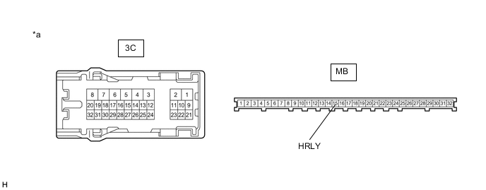
*a Component without harness connected
(Instrument Panel Junction Block Assembly)
- -
-
Remove the instrument panel junction block assembly.
-
Remove the main body ECU (multiplex network body ECU) from the instrument panel junction block assembly.
-
Measure the resistance according to the value(s) in the table below.
Standard Resistance Tester Connection Condition Specified Condition 3C-31 - MB-15 (HRLY) Always Below 1 Ω Result Proceed to OK NG
OK
REPLACE MAIN BODY ECU (MULTIPLEX NETWORK BODY ECU) Click here
NG
REPLACE INSTRUMENT PANEL JUNCTION BLOCK ASSEMBLY Click here
-
-
INSPECT HEADLIGHT ASSEMBLY RH (LO TERMINAL VOLTAGE)

*a Front view of wire harness connector
(to Headlight Assembly RH)
-
Disconnect the A73 headlight assembly RH connector.
-
Measure the voltage according to the value(s) in the table below.
Standard Voltage Tester Connection Condition Specified Condition A73-3 (LO) - Body ground Light control switch in head position 11 to 14 V Result Proceed to OK NG
NG
CHECK HARNESS AND CONNECTOR (H-LP RH RELAY - HEADLIGHT ASSEMBLY RH) Click here
OK
-
-
CHECK HARNESS AND CONNECTOR (HEADLIGHT ASSEMBLY RH - BODY GROUND)
-
Measure the resistance according to the value(s) in the table below.
Standard Resistance Tester Connection Condition Specified Condition A73-1 (E) - Body ground Always Below 1 Ω Result Proceed to OK NG
NG
REPAIR OR REPLACE HARNESS OR CONNECTOR
OK
-
-
INSPECT HEADLIGHT ASSEMBLY RH (S TERMINAL VOLTAGE)
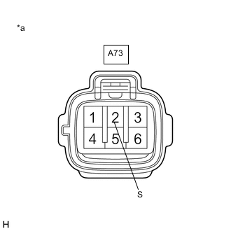
*a Front view of wire harness connector
(to Headlight Assembly RH)
-
Measure the voltage according to the value(s) in the table below.
Standard Voltage Tester Connection Condition Specified Condition A73-2 (S) - Body ground Ignition switch ON 11 to 14 V Result Proceed to OK NG
NG
CHECK HARNESS AND CONNECTOR (HEADLIGHT ASSEMBLY RH - MAIN BODY ECU (MULTIPLEX NETWORK BODY ECU)) Click here
OK
-
-
INSPECT HEADLIGHT UNIT ASSEMBLY RH
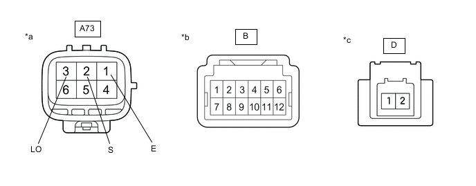
*a Component without harness connected
(to Wire Harness)
*b Component without harness connected
(to Light Control ECU)
*c Component without harness connected
(to Headlight LED Unit Assembly RH)
- -
-
Remove the headlight assembly RH.
-
Remove the headlight unit assembly RH.
-
Measure the resistance according to the value(s) in the table below.
Standard Resistance Tester Connection Condition Specified Condition A73-1 (E) - B-6 Always Below 1 Ω A73-2 (S) - B-12 Always Below 1 Ω A73-3 (LO) - B-7 Always Below 1 Ω B-4 - D-1 Always Below 1 Ω B-10 - D-2 Always Below 1 Ω Result Proceed to OK NG
NG
REPLACE HEADLIGHT UNIT ASSEMBLY RH Click here
OK
-
-
CHECK LIGHT CONTROL ECU
-
Remove each light control ECU, interchange the light control ECU (for RH) with (for LH) and connect the connectors.
Result Proceed to NEXT
NEXT
-
-
CLEAR DTC
-
Connect the GTS to the DLC3.
-
Turn the ignition switch to ON.
-
Turn the GTS on.
-
Enter the following menus: Body Electrical / Main Body / Trouble Codes.
-
Clear the DTCs.
Body Electrical > Main Body > Clear DTCsResult Proceed to NEXT
NEXT
-
-
CHECK FOR DTC
-
Connect the GTS to the DLC3.
-
Start the engine.
-
Operate the light control switch to turn on the low beam headlights and wait 10 seconds or more.
-
Turn the GTS on.
-
Enter the following menus: Body Electrical / Main Body / Trouble Codes.
-
Check for DTCs.
Body Electrical > Main Body > Trouble CodesResult Result Proceed to DTC B2431 is output A DTC B2430 is output B
A
REPLACE HEADLIGHT LED UNIT ASSEMBLY RH Click here
B
REPLACE LIGHT CONTROL ECU Click here
-
-
CHECK HARNESS AND CONNECTOR (HEADLIGHT ASSEMBLY RH - MAIN BODY ECU (MULTIPLEX NETWORK BODY ECU))
-
Disconnect the K51 main body ECU (multiplex network body ECU) connector.
-
Measure the resistance according to the value(s) in the table below.
Standard Resistance Tester Connection Condition Specified Condition A73-2 (S) - K51-15 (RLEW) Always Below 1 Ω A73-2 (S) or K51-15 (RLEW) - Body ground Always 10 kΩ or higher Result Proceed to OK NG
OK
REPLACE MAIN BODY ECU (MULTIPLEX NETWORK BODY ECU) Click here
NG
REPAIR OR REPLACE HARNESS OR CONNECTOR
-
-
CHECK HARNESS AND CONNECTOR (H-LP RH RELAY - HEADLIGHT ASSEMBLY RH)
-
Remove the H-LP RH relay.
-
Measure the resistance according to the value(s) in the table below.
Standard Resistance Tester Connection Condition Specified Condition 3 (H-LP RH relay) - A73-3 (LO) Always Below 1 Ω 3 (H-LP RH relay) or A73-3 (LO) - Body ground Always 10 kΩ or higher Result Proceed to OK NG
NG
REPAIR OR REPLACE HARNESS OR CONNECTOR
OK
-
-
INSPECT H-LP RH RELAY
-
Inspect the H-LP RH relay.
Result Proceed to OK NG
NG
REPLACE H-LP RH RELAY
OK
-
-
CHECK HARNESS AND CONNECTOR (POWER SOURCE - H-LP RH RELAY)
-
Measure the voltage according to the value(s) in the table below.
Standard Voltage Tester Connection Condition Specified Condition 2 (H-LP RH relay) - Body ground Always 11 to 14 V 5 (H-LP RH relay) - Body ground Always 11 to 14 V Result Proceed to OK NG
NG
REPAIR OR REPLACE HARNESS OR CONNECTOR
OK
-
-
CHECK HARNESS AND CONNECTOR (H-LP RH RELAY - MAIN BODY ECU (MULTIPLEX NETWORK BODY ECU))
-
Disconnect the K52 main body ECU (multiplex network body ECU) connector.
-
Measure the resistance according to the value(s) in the table below.
Standard Resistance Tester Connection Condition Specified Condition 1 (H-LP RH relay) - K52-12 (HRY2) Always Below 1 Ω 1 (H-LP RH relay) or K52-12 (HRY2) - Body ground Always 10 kΩ or higher Result Proceed to OK NG
OK
REPLACE MAIN BODY ECU (MULTIPLEX NETWORK BODY ECU) Click here
NG
REPAIR OR REPLACE HARNESS OR CONNECTOR
-