POWER MIRROR CONTROL SYSTEM(w/ Memory) Power Mirror cannot be Adjusted with Power Mirror Switch
DESCRIPTION
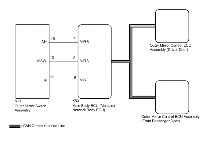
The outer mirror switch assembly sends the mirror adjust switch signals to the main body ECU (multiplex network body ECU). The main body ECU (multiplex network body ECU) then sends the received mirror adjust switch signals to each outer mirror control ECU assembly via CAN communication. Based on this signal, each outer mirror control ECU assembly operates the vertical and horizontal mirror motors to adjust the mirror surface position.
WIRING DIAGRAM
CAUTION / NOTICE / HINT
Note
-
The power mirror control system (w/ Memory) uses the CAN communication system and LIN communication system. Inspect the communication functions by following How to Proceed with Troubleshooting. Troubleshoot the power window control system after confirming that the communication systems are functioning properly.
-
Before replacing the main body ECU (multiplex network body ECU), refer to Service Bulletin.
-
The vehicle battery supplies power to the main body ECU (multiplex network body ECU) via the door control battery. Therefore, before performing this troubleshooting procedure, make sure to perform an on-vehicle inspection to confirm that the main body ECU (multiplex network body ECU) power source circuit is normal.
PROCEDURE
-
READ VALUE USING GTS
-
Connect the GTS to the DLC3.
-
Turn the engine switch on (IG).
-
Turn the GTS on.
-
Enter the following menus: Body Electrical / Main Body / Data List.
-
Read the Data List according to the display on the GTS.
Body Electrical > Main Body > Data ListTester Display Measurement Item Range Normal Condition Diagnostic Note Mirror Selection SW (R) Mirror select switch signal for RH mirror OFF or ON OFF: Mirror select switch off
ON: Mirror select switch R switch on
- Mirror Selection SW (L) Mirror select switch signal for LH mirror OFF or ON OFF: Mirror select switch off
ON: Mirror select switch L switch on
- Mirror Position SW (R) Mirror adjust switch signal (Right) OFF or ON OFF: Mirror adjust switch not pushed right
ON: Mirror adjust switch pushed right
Check with the mirror select switch L or R selected Mirror Position SW (L) Mirror adjust switch signal (Left) OFF or ON OFF: Mirror adjust switch not pushed left
ON: Mirror adjust switch pushed left
Check with the mirror select switch L or R selected Mirror Position SW (Up) Mirror adjust switch signal (Up) OFF or ON OFF: Mirror adjust switch not pushed up
ON: Mirror adjust switch pushed up
Check with the mirror select switch L or R selected Mirror Position SW (Dwn) Mirror adjust switch signal (Down) OFF or ON OFF: Mirror adjust switch not pushed down
ON: Mirror adjust switch pushed down
Check with the mirror select switch L or R selected
Body Electrical > Main Body > Data ListTester Display Mirror Selection SW (R) Mirror Selection SW (L) Mirror Position SW (R) Mirror Position SW (L) Mirror Position SW (Up) Mirror Position SW (Dwn) OK On the GTS screen, ON or OFF is displayed accordingly. Result Proceed to OK NG
OK 
REPLACE MAIN BODY ECU (MULTIPLEX NETWORK BODY ECU) Click here
NG 
-
-
INSPECT OUTER MIRROR SWITCH ASSEMBLY
-
Remove the outer mirror switch assembly.
-
Inspect the outer mirror switch assembly.
Result Proceed to OK NG
NG
REPLACE OUTER MIRROR SWITCH ASSEMBLY Click here
OK
-
-
CHECK HARNESS AND CONNECTOR (OUTER MIRROR SWITCH ASSEMBLY - MAIN BODY ECU (MULTIPLEX NETWORK BODY ECU))
-
Disconnect the N21 outer mirror switch assembly.
-
Disconnect the K53 main body ECU (multiplex network body ECU).
-
Measure the resistance according to the value(s) in the table below.
Standard Resistance Tester Connection Condition Specified Condition N21-12 (E) - K53-9 (MIRE) Always Below 1 Ω N21-15 (M+) - K53-7 (MIRB) Always Below 1 Ω N21-13 (MSW) - K53-8 (MIRS) Always Below 1 Ω N21-12 (E) or K53-9 (MIRE) - Body ground Always 10 kΩ or higher N21-15 (M+) or K53-7 (MIRB) - Body ground Always 10 kΩ or higher N21-13 (MSW) or K53-8 (MIRS) - Body ground Always 10 kΩ or higher Result Proceed to OK NG
OK
REPLACE MAIN BODY ECU (MULTIPLEX NETWORK BODY ECU) Click here
NG
REPAIR OR REPLACE HARNESS OR CONNECTOR
-