Click here
-
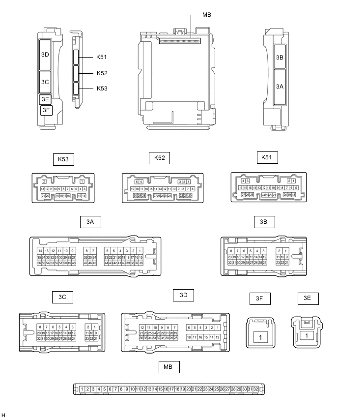
CHECK INSTRUMENT PANEL JUNCTION BLOCK ASSEMBLY AND MAIN BODY ECU (MULTIPLEX NETWORK BODY ECU)
-
Remove the main body ECU (multiplex network body ECU) from the instrument panel junction block assembly.
-
Reconnect the instrument panel junction block assembly connectors.
-
Measure the voltage and resistance according to the value(s) in the table below.
Tip:Measure the values on the wire harness side with the connector disconnected.
Terminal No. (Symbol) Wiring Color Terminal Description Condition Specified Condition MB-11 (GND1) - Body ground - Ground Always Below 1 Ω MB-31 (BECU) - Body ground - Battery power supply Always 11 to 14 V MB-32 (IG) - Body ground - IG power supply Ignition switch off Below 1 V Ignition switch ON 11 to 14 V MB-30 (ACC) - Body ground - ACC power supply Ignition switch off Below 1 V Ignition switch ACC 11 to 14 V -
Install the main body ECU (multiplex network body ECU) to the instrument panel junction block assembly.
-
Measure the voltage according to the value(s) in the table below.
Terminal No. (Symbol) Wiring Color Terminal Description Condition Specified Condition K51-6 (REV) - Body ground B - Body ground Reverse signal Ignition switch ON, shift lever in any position other than R 11 to 14 V Ignition switch ON, shift lever in R Below 1 V
-
-

CHECK REAR WINDOW SHADE ASSEMBLY
-
Disconnect the R64 rear window shade assembly connector.
-
Measure the voltage and resistance according to the value(s) in the table below.
Tip:Measure the values on the wire harness side with the connector disconnected.
Terminal No. (Symbol) Wiring Color Terminal Description Condition Specified Condition R64-8 (B) - Body ground LA-G - Body ground Battery power supply Always 11 to 14 V R64-7 (IG) - Body ground B - Body ground IG power supply Ignition switch off Below 1 V Ignition switch ON 11 to 14 V R64-1 (E) - Body ground LA - Body ground Ground Always Below 1 Ω -
Reconnect the R64 rear window shade assembly connector.
-
Measure the voltage according to the value(s) in the table below.
Terminal No. (Symbol) Wiring Color Terminal Description Condition Specified Condition R64-3 (REV) - R64-1 (E) LG - LA Reverse signal Ignition switch ON, shift lever in any position other than R 11 to 14 V Ignition switch ON, shift lever in R Below 1 V R64-5 (SW) - R64-1 (E) GR - LA Rear window shade assembly operation signal Procedure:
-
Ignition switch ON
-
Select Open or Close on the rear sunshade screen of the multi-information display.
5.5 V or higher → Below 1 V → 5.5 V or higher R64-4 (RSW) - R64-1 (E) BE - LA Rear window shade assembly operation signal Ignition switch ON, rear sunshade switch (cooler control switch assembly) not touched 5.5 V or higher Ignition switch ON, rear sunshade switch (cooler control switch assembly) touched 5.5 V or higher → Below 1 V → 5.5 V or higher -
-
-
CHECK COMBINATION METER ASSEMBLY
-
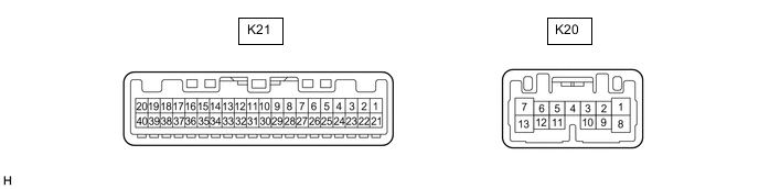
Disconnect the K21 combination meter assembly connector.
-
Measure the voltage and resistance according to the value(s) in the table below.
Tip:Measure the values on the wire harness side with the connector disconnected.
Terminal No. (Symbol) Wiring Color Terminal Description Condition Specified Condition K21-40 (B) - Body ground LA-B - Body ground Battery power supply Always 11 to 14 V K21-39 (IG+) - Body ground LA-GR - Body ground IG power supply Ignition switch off Below 1 V Ignition switch ON 11 to 14 V K21-21 (ES) - Body ground W-B - Body ground Ground Always Below 1 Ω -
Reconnect the K21 combination meter assembly connector.
-
Measure the voltage according to the value(s) in the table below.
Terminal No. (Symbol) Wiring Color Terminal Description Condition Specified Condition K21-22 (ECU) - Body ground BE - Body ground Rear window shade assembly operation signal Procedure:
-
Ignition switch ON
-
Select Open or Close on the rear sunshade screen of the multi-information display.
5.5 V or higher → Below 1 V → 5.5 V or higher -
-