AIR CONDITIONING UNIT REMOVAL
CAUTION / NOTICE / HINT
The necessary procedures (adjustment, calibration, initialization or registration) that must be performed after parts are removed and installed, or replaced during air conditioning unit removal/installation are shown below.
| Replaced Part or Performed Procedure | Necessary Procedure | Effect/Inoperative Function When Necessary Procedures are not Performed | Link |
|---|---|---|---|
| Disconnect cable from negative battery terminal | Perform steering sensor zero point calibration | Lane departure alert system (w/ Steering Control) | |
| Pre-collision system | |||
| Memorize steering angle neutral point | Parking assist monitor system | ||
| Steering sensor |
|
Parking assist monitor system | Click here for Initialization Click here for Calibration |
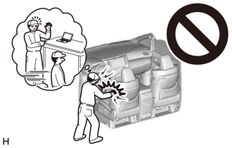
CAUTION:
Some of these service operations affect the SRS airbag system. Read the precautionary notices concerning the SRS airbag system before servicing.
PROCEDURE
-
PRECAUTION
Note
Make sure to select face mode before disconnecting the cable from the negative (-) battery terminal.
-
RECOVER REFRIGERANT FROM REFRIGERATION SYSTEM
-
REMOVE WINDSHIELD WIPER MOTOR AND LINK ASSEMBLY
-
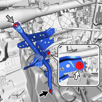
REMOVE FRONT CENTER UPPER SUSPENSION BRACE SUB-ASSEMBLY
for LHD:
for RHD:
-
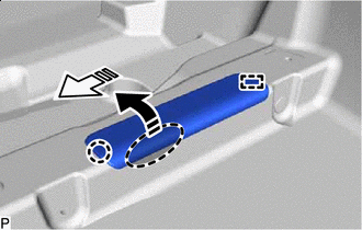
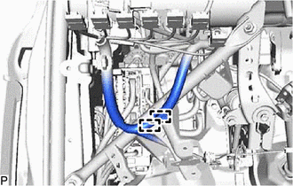
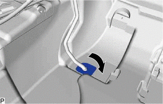
DISCONNECT OUTLET HEATER WATER HOSE
-
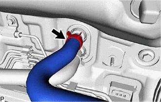
Using pliers, grip the claws of the clip and slide the clip to disconnect the outlet heater water hose.
Note
-
Do not apply excessive force to the outlet heater water hose.
-
Prepare a drain pan or cloth in case the coolant leaks.
-
-
-
DISCONNECT INLET HEATER WATER HOSE
-
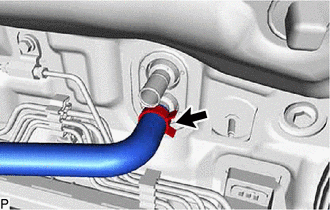
Using pliers, grip the claws of the clip and slide the clip to disconnect the inlet heater water hose.
Note
-
Do not apply excessive force to the inlet heater water hose.
-
Prepare a drain pan or cloth in case the coolant leaks.
-
-
-
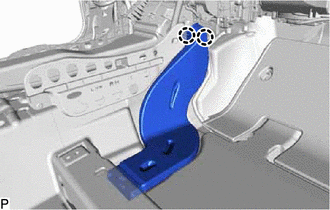
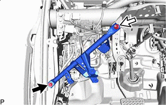
DISCONNECT SUCTION PIPE SUB-ASSEMBLY
-
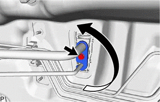
Remove the bolt and rotate the hook connector as shown in the illustration.
-
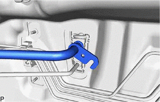
Disconnect the suction pipe sub-assembly.
-
Remove the O-ring from the suction pipe sub-assembly.
Note
Seal the openings of the disconnected parts using vinyl tape to prevent entry of moisture and foreign matter.
-
-
DISCONNECT AIR CONDITIONING TUBE AND ACCESSORY ASSEMBLY
-
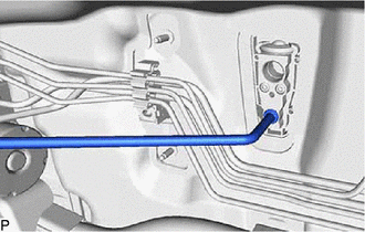
Disconnect the air conditioning tube and accessory assembly.
-
Remove the O-ring from the air conditioning tube and accessory assembly.
Note
Seal the openings of the disconnected parts using vinyl tape to prevent entry of moisture and foreign matter.
-
-
REMOVE FRONT SEAT ASSEMBLY LH
for Manual Seat:
for Power Seat:
-
REMOVE FRONT SEAT ASSEMBLY RH
Tech Tips
Use the same procedure as for the LH side.
-
REMOVE TRANSMISSION FLOOR SHIFT ASSEMBLY
for UA80E:
for UB80E:
for U760E:
-
REMOVE STEERING COLUMN ASSEMBLY
for Manual Tilt and Manual Telescopic Steering Column:
for Power Tilt and Power Telescopic Steering Column:
-
REMOVE INSTRUMENT PANEL SAFETY PAD SUB-ASSEMBLY
-
REMOVE NO. 1 CLEARANCE WARNING BUZZER (for LHD)
w/ TOYOTA Parking Assist-sensor System:
-
REMOVE DOOR CONTROL BATTERY (w/ Door Control Battery)
-
REMOVE CENTRAL GATEWAY ECU (NETWORK GATEWAY ECU) (w/o Smart Entry and Start System)
for LHD:
for RHD:
-
REMOVE ECU INTEGRATION BOX RH (for LHD)
w/ ECU Integration Box RH:
-
REMOVE INSTRUMENT PANEL JUNCTION BLOCK ASSEMBLY WITH MAIN BODY ECU (for RHD)
-
REMOVE COOLER (ROOM TEMP. SENSOR) THERMISTOR (for Automatic Air Conditioning System)
-
Disconnect the connector and aspirator to remove the cooler (room temp. sensor) thermistor.
-
-
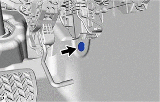
REMOVE ACCELERATOR PEDAL PAD
for 2AR-FE:
for A25A-FKS:
for 2GR-FKS:
-
REMOVE ACCELERATOR PEDAL
for 2AR-FE:
for A25A-FKS:
for 2GR-FKS:
-
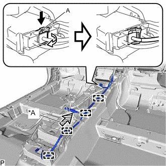
REMOVE FRONT FLOOR CAUTION PLATE COVER
-

Place Hand Here 
Remove in this Direction (1) 
Remove in this Direction (2) Disengage the claw as shown by the arrow (1), and then pull the front floor caution plate cover as shown by the arrow (2) in the illustration to disengage the guide and remove it.
-
-
REMOVE REAR NO. 2 AIR DUCT
-
for LHD:
-
Remove the front floor carpet clip.
-
-
Remove the front floor carpet clip.
-
Disengage the 2 guides and turn back the front floor carpet assembly as shown in the illustration.
-
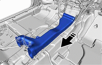
Remove in this Direction Disengage the 4 claws and remove the rear No. 2 air duct as shown in the illustration.
-
-
REMOVE REAR NO. 1 AIR DUCT
-
Disengage the 2 claws and remove the rear No. 1 air duct.
-
-
REMOVE REAR NO. 4 AIR DUCT
-
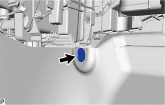
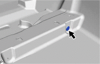
Remove the front floor carpet clip.
-
Remove the front floor carpet clip.
-
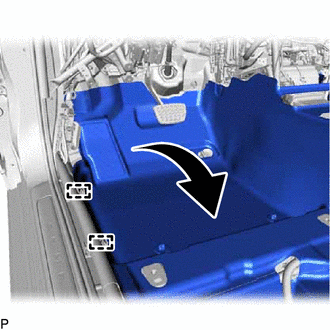
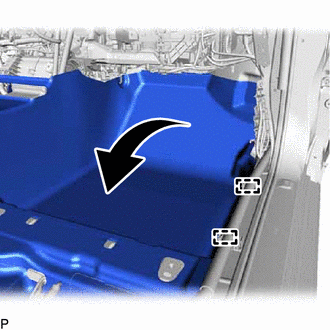
Disengage the 2 guides and turn back the front floor carpet assembly as shown in the illustration.
-
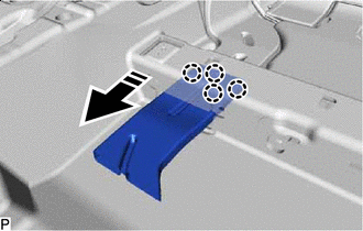
Remove in this Direction Disengage the 4 claws and remove the rear No. 4 air duct as shown in the illustration.
-
-
REMOVE REAR NO. 3 AIR DUCT
-
Disengage the 2 claws and remove the rear No. 3 air duct.
-
-
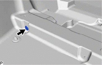
REMOVE FLOOR CARPET BRACKET RH
-
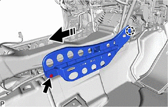
Remove in this Direction Remove the clip.
-
Disengage the claw to remove the floor carpet bracket RH as shown in the illustration.
-
-
REMOVE FLOOR CARPET BRACKET LH
-
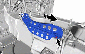
Remove in this Direction Remove the clip.
-
Disengage the claw to remove the floor carpet bracket LH as shown in the illustration.
-
-
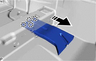
REMOVE NO. 1 CONSOLE BOX DUCT
-
Remove in this Direction Remove the No. 1 console box duct as shown in the illustration.
-
-
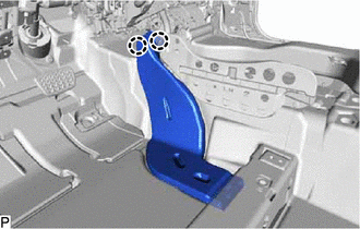
REMOVE NO. 3 DASH PANEL INSULATOR PAD
-
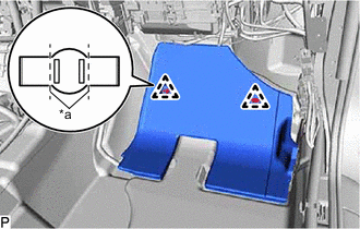
*a Cut Cut each claw of the 2 clips and remove the No. 3 dash panel insulator pad.
Note
If the No. 3 dash panel insulator pad is damaged, replace it with a new one.
-
Remove the 2 clips.
-
-
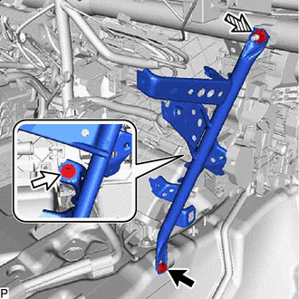
REMOVE NO. 1 INSTRUMENT PANEL BRACE SUB-ASSEMBLY
-
for LHD:
-
*a Earth Wire Remove the bolt and disconnect the earth wire.
-
Disengage each clamp.
-
-
for RHD:
-
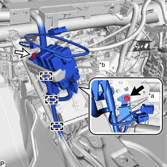
*a Earth Wire *b Relay Block Assembly 
Bolt (A) 
Bolt (B) Remove the bolt (A) and disconnect the earth wire.
-
Remove the bolt (B).
-
Disengage each clamp to separate the relay block assembly.
-
-
Bolt Screw 
Nut Remove the bolt, screw, nut and No. 1 instrument panel brace sub-assembly.
-
-
REMOVE NO. 2 INSTRUMENT PANEL BRACE SUB-ASSEMBLY
-
for LHD:
-
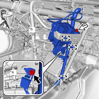
*a Earth Wire *b Relay Block Assembly Bolt (A) Bolt (B) Remove the bolt (A) and disconnect the earth wire.
-
Remove the bolt (B).
-
Disengage each clamp to separate the relay block assembly.
-
-
for RHD:
-
*a Earth Wire Remove the bolt and disconnect the earth wire.
-
Disengage each clamp.
-
-
Bolt Screw Nut Remove the bolt, screw, nut and No. 2 instrument panel brace sub-assembly.
-
-
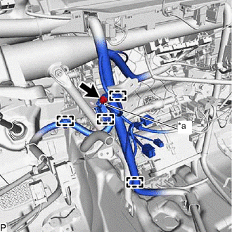
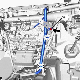
REMOVE NO. 3 INSTRUMENT PANEL TO COWL BRACE SUB-ASSEMBLY
-
Disengage each clamp.
-
Bolt Nut Remove the bolt, nut and No. 3 instrument panel to cowl brace sub-assembly.
-
-
REMOVE INSTRUMENT PANEL JUNCTION BLOCK ASSEMBLY WITH MAIN BODY ECU (for LHD)
-
REMOVE ECU INTEGRATION BOX RH (for RHD)
w/ ECU Integration Box RH:
-
REMOVE NO. 2 AIR DUCT SUB-ASSEMBLY
-
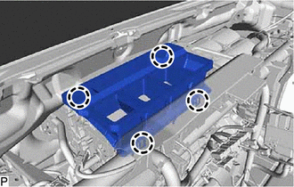
Disengage the 4 claws to remove the No. 2 air duct sub-assembly.
-
-
REMOVE INSTRUMENT PANEL REINFORCEMENT ASSEMBLY WITH AIR CONDITIONER UNIT ASSEMBLY
Note
-
Be sure to support the air conditioner unit assembly when removing it. Failure to do so may cause the bracket of the air conditioner unit assembly to break.
-
When disassembling the air conditioner unit assembly, eliminate static electricity by touching the vehicle body to prevent the components from being damaged.
-
for LHD:
-
Disconnect the connector.
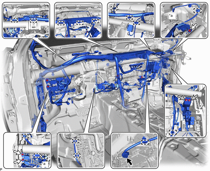
*a Earth Wire *b Connector Holder Connector Bolt Nut - - -
Remove the 3 bolts and disconnect the 3 earth wires.
-
Remove the 2 nuts and disconnect the connector holder.
-
Disengage each clamp.
-
-
for RHD:
-
Disconnect each connector.
*a Earth Wire - - Connector Bolt -
Remove the 3 bolts and disconnect the 3 earth wires.
-
Disengage each clamp.
-
*a Connector Holder Remove the 2 nuts and disconnect the connector holder.
-
Disengage the clamp.
-
-
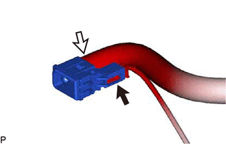
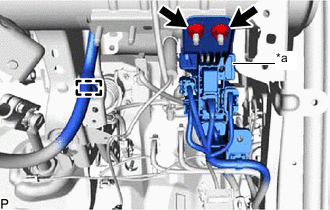
*A w/ Smart Entry and Start System Release the lock (1) Release the lock (2) Push down the part (A) in the direction indicated by the arrow (1), to release the lock, and then move the lock lever in the direction indicated by the arrow (2) shown in the illustration to disconnect the connector.
Note
When disconnecting any airbag connector, take care not to damage the airbag wire harness.
-
w/ Smart Entry and Start System:
-
Disconnect the connector.
-
-
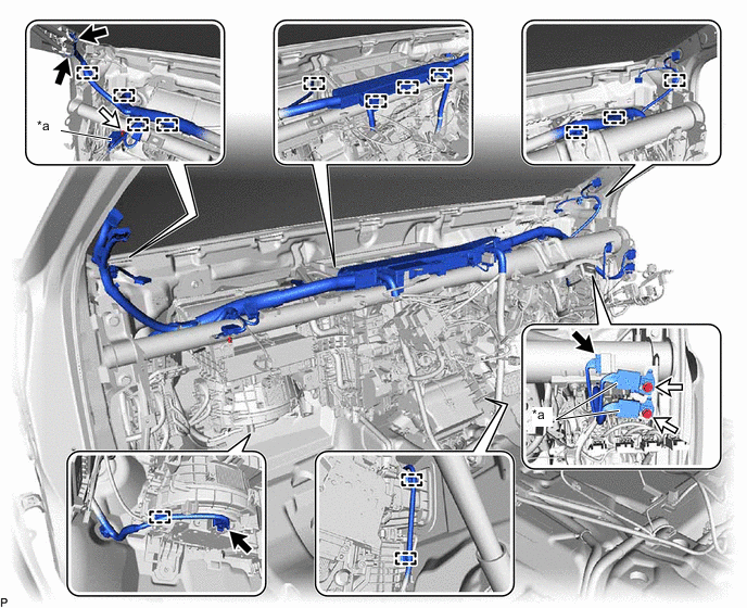
Disengage each clamp to separate the instrument panel wire.
-
Turn back the front floor mat as shown in the illustration.
-
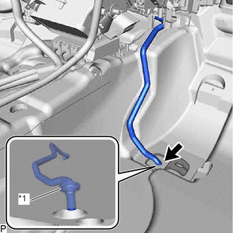
*1 Cooler Unit Drain Hose Grommet Disconnect the drain cooler hose.
Note
If the drain cooler hose is disconnected from the cooler unit drain hose grommet, make sure to replace the cooler unit drain hose grommet with a new one. Failure to do so may lead to water ingress.
-
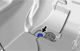
Remove the cooler unit drain hose grommet.
-
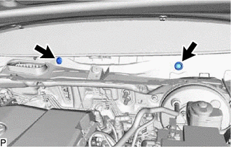
Remove the 2 hole plugs.
-
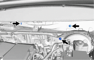
Remove the 3 bolts.
-
Remove the 4 bolts (A).
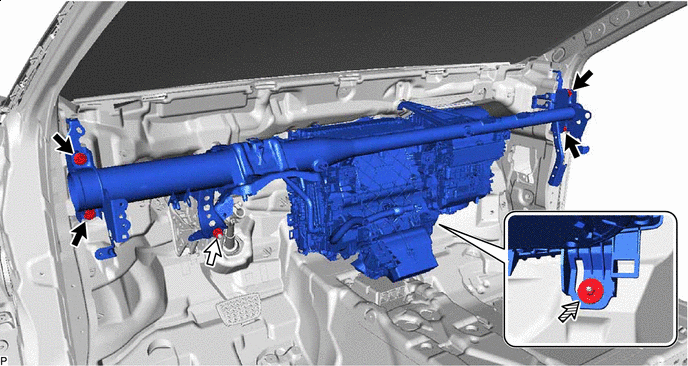
Bolt (A) Bolt (B) Nut - - -
Remove the bolt (B) and disconnect the brake pedal assembly.
-
Remove the nut.
-
Disengage each clamp.
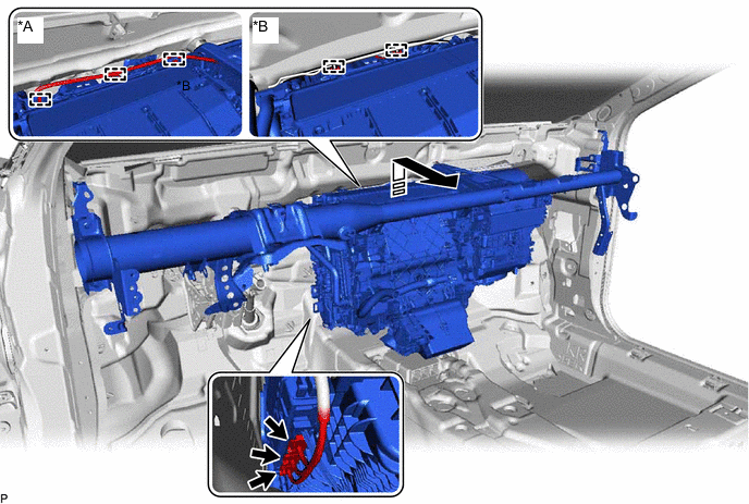
*A for LHD *B for RHD Remove in this Direction - - -
Disconnect each connector.
-
Remove the instrument panel reinforcement assembly with air conditioner unit assembly as shown in the illustration.
-
-
REMOVE AIR CONDITIONER UNIT ASSEMBLY
-
Remove the 3 bolts.
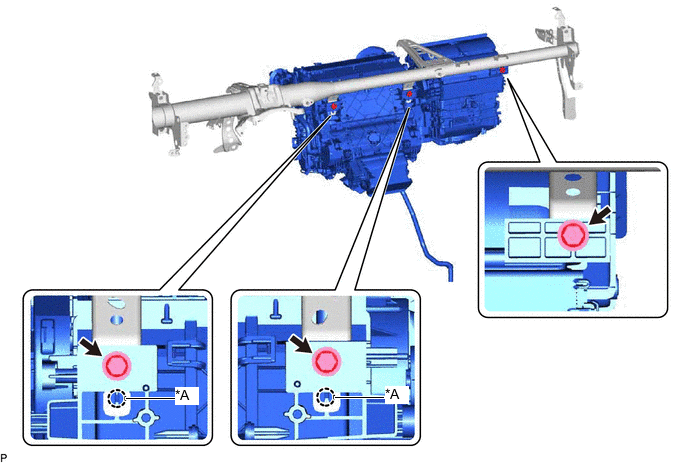
*A w/ Claw - - -
w/ Claw:
-
Disengage the 2 claws.
-
-
Remove the air conditioner unit assembly from the instrument panel reinforcement assembly.
-