LIGHTING SYSTEM Footwell Light Circuit
DESCRIPTION
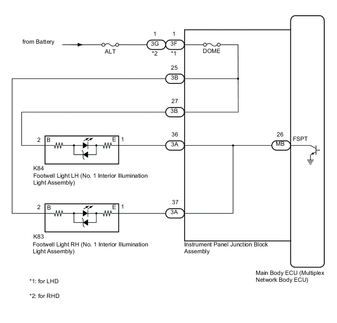
The main body ECU (multiplex network body ECU) controls the operation of the following lights:
-
Footwell Light LH (No. 1 Interior Illumination Light Assembly)
-
Footwell Light RH (No. 1 Interior Illumination Light Assembly)
WIRING DIAGRAM
CAUTION / NOTICE / HINT
Note
-
Inspect the fuses for circuits related to this system before performing the following procedure.
-
Before replacing the main body ECU (multiplex network body ECU), refer to Service Bulletin.*1
-
The vehicle battery supplies power to the main body ECU (multiplex network body ECU) via the door control battery. Therefore, before performing this troubleshooting procedure, make sure to perform an on-vehicle inspection to confirm that the main body ECU (multiplex network body ECU) power source circuit is normal.*2
-
*1: w/ Smart Entry and Start System
-
*2: w/ Door Control Battery
PROCEDURE
-
PERFORM ACTIVE TEST USING GTS
-
Connect the GTS to the DLC3.
-
Turn the ignition switch to ON.
-
Turn the GTS on.
-
Enter the following menus: Body Electrical / Main Body / Active Test.
-
Perform the Active Test according to the display on the GTS.
Body Electrical > Main Body > Active TestTester Display Measurement Item Control Range Diagnostic Note Fr Foot Light Footwell light (No. 1 interior illumination light assembly) OFF or ON Preconditions for using the Active Test to check dimmer controlled illumination:
-
Ignition switch ON
-
Shift lever is in any position other than P
Body Electrical > Main Body > Active TestTester Display Fr Foot Light OK Footwell lights come on. Result Result Proceed to OK A NG (Footwell light LH does not come on) B NG (Footwell light RH does not come on) C NG (Footwell light LH and RH do not come on) D -
A 
USE SIMULATION METHOD TO CHECK Click here
C 
INSPECT FOOTWELL LIGHT RH (NO. 1 INTERIOR ILLUMINATION LIGHT ASSEMBLY) Click here
D
CHECK HARNESS AND CONNECTOR (POWER SOURCE - INSTRUMENT PANEL JUNCTION BLOCK ASSEMBLY) Click here
B 
-
-
INSPECT FOOTWELL LIGHT LH (NO. 1 INTERIOR ILLUMINATION LIGHT ASSEMBLY)
-
Remove the footwell light LH (No. 1 interior illumination light assembly).
-
Inspect the footwell light LH (No. 1 interior illumination light assembly).
Result Proceed to OK NG
NG
REPLACE FOOTWELL LIGHT LH (NO. 1 INTERIOR ILLUMINATION LIGHT ASSEMBLY) Click here
OK
-
-
CHECK HARNESS AND CONNECTOR (FOOTWELL LIGHT LH (NO. 1 INTERIOR ILLUMINATION LIGHT ASSEMBLY) - INSTRUMENT PANEL JUNCTION BLOCK ASSEMBLY)
-
Disconnect the 3A and 3B instrument panel junction block assembly connectors.
-
Measure the resistance according to the value(s) in the table below.
Standard Resistance Tester Connection Condition Specified Condition K84-1 (E) - 3A-36 Always Below 1 Ω K84-2 (B) - 3B-27 Always Below 1 Ω K84-1 (E) or 3A-36 - Body ground Always 10 kΩ or higher K84-2 (B) or 3B-27 - Body ground Always 10 kΩ or higher Result Proceed to OK NG
NG
REPAIR OR REPLACE HARNESS OR CONNECTOR
OK
-
-
CHECK INSTRUMENT PANEL JUNCTION BLOCK ASSEMBLY
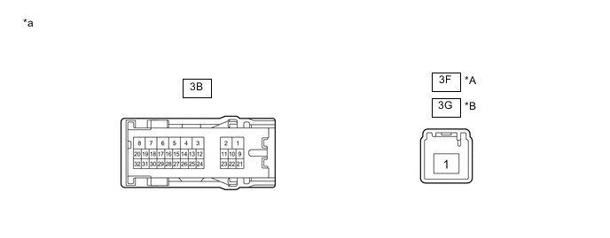
*A for LHD *B for RHD *a Component without harness connected
(Instrument Panel Junction Block Assembly)
- -
-
Disconnect the 3F*1 or 3G*2 instrument panel junction block assembly connector.
-
Measure the resistance according to the value(s) in the table below.
Standard Resistance Tester Connection Condition Specified Condition 3B-27 - 3F-1*1 Always Below 1 Ω 3B-27 - 3G-1*2 Always Below 1 Ω
-
*1: for LHD
-
*2: for RHD
Result Proceed to OK NG -
NG
REPLACE INSTRUMENT PANEL JUNCTION BLOCK ASSEMBLY Click here
OK
-
-
INSPECT INSTRUMENT PANEL JUNCTION BLOCK ASSEMBLY
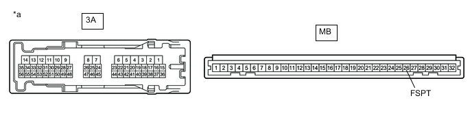
*a Component without harness connected
(Instrument Panel Junction Block Assembly)
- -
-
Remove the instrument panel junction block assembly.
-
Remove the main body ECU (multiplex network body ECU) from the instrument panel junction block assembly.
-
Measure the resistance according to the value(s) in the table below.
Standard Resistance Tester Connection Condition Specified Condition 3A-36 - MB-26 (FSPT) Always Below 1 Ω Result Proceed to OK NG
OK
REPLACE MAIN BODY ECU (MULTIPLEX NETWORK BODY ECU) Click here
NG
REPLACE INSTRUMENT PANEL JUNCTION BLOCK ASSEMBLY Click here
-
-
INSPECT FOOTWELL LIGHT RH (NO. 1 INTERIOR ILLUMINATION LIGHT ASSEMBLY)
-
Remove the footwell light RH (No. 1 interior illumination light assembly).
-
Inspect the footwell light RH (No. 1 interior illumination light assembly).
Result Proceed to OK NG
NG
REPLACE FOOTWELL LIGHT RH (NO. 1 INTERIOR ILLUMINATION LIGHT ASSEMBLY) Click here
OK
-
-
CHECK HARNESS AND CONNECTOR (FOOTWELL LIGHT RH (NO. 1 INTERIOR ILLUMINATION LIGHT ASSEMBLY) - INSTRUMENT PANEL JUNCTION BLOCK ASSEMBLY)
-
Disconnect the 3A and 3B instrument panel junction block assembly connectors.
-
Measure the resistance according to the value(s) in the table below.
Standard Resistance Tester Connection Condition Specified Condition K83-1 (E) - 3A-37 Always Below 1 Ω K83-2 (B) - 3B-25 Always Below 1 Ω K83-1 (E) or 3A-37 - Body ground Always 10 kΩ or higher K83-2 (B) or 3B-25 - Body ground Always 10 kΩ or higher Result Proceed to OK NG
NG
REPAIR OR REPLACE HARNESS OR CONNECTOR
OK
-
-
CHECK INSTRUMENT PANEL JUNCTION BLOCK ASSEMBLY
*A for LHD *B for RHD *a Component without harness connected
(Instrument Panel Junction Block Assembly)
- -
-
Disconnect the 3F*1 or 3G*2 instrument panel junction block assembly connector.
-
Measure the resistance according to the value(s) in the table below.
Standard Resistance Tester Connection Condition Specified Condition 3B-25 - 3F-1*1 Always Below 1 Ω 3B-25 - 3G-1*2 Always Below 1 Ω
-
*1: for LHD
-
*2: for RHD
Result Proceed to OK NG -
NG
REPLACE INSTRUMENT PANEL JUNCTION BLOCK ASSEMBLY Click here
OK
-
-
INSPECT INSTRUMENT PANEL JUNCTION BLOCK ASSEMBLY
*a Component without harness connected
(Instrument Panel Junction Block Assembly)
- -
-
Remove the instrument panel junction block assembly.
-
Remove the main body ECU (multiplex network body ECU) from the instrument panel junction block assembly.
-
Measure the resistance according to the value(s) in the table below.
Standard Resistance Tester Connection Condition Specified Condition 3A-37 - MB-26 (FSPT) Always Below 1 Ω Result Proceed to OK NG
OK
REPLACE MAIN BODY ECU (MULTIPLEX NETWORK BODY ECU) Click here
NG
REPLACE INSTRUMENT PANEL JUNCTION BLOCK ASSEMBLY Click here
-
-
CHECK HARNESS AND CONNECTOR (POWER SOURCE - INSTRUMENT PANEL JUNCTION BLOCK ASSEMBLY)
-
Disconnect the 3F*1 or 3G*2 instrument panel junction block assembly connector.
-
Measure the voltage according to the value(s) in the table below.
Standard Voltage Tester Connection Condition Specified Condition 3F-1 - Body ground*1 Always 11 to 14 V 3G-1 - Body ground*2 Always 11 to 14 V
-
*1: for LHD
-
*2: for RHD
Result Proceed to OK NG -
NG
REPAIR OR REPLACE HARNESS OR CONNECTOR
OK
-
-
CHECK INSTRUMENT PANEL JUNCTION BLOCK ASSEMBLY
*A for LHD *B for RHD *a Component without harness connected
(Instrument Panel Junction Block Assembly)
- -
-
Disconnect the 3B instrument panel junction block assembly connector.
-
Measure the resistance according to the value(s) in the table below.
Standard Resistance Tester Connection Condition Specified Condition 3B-27 or 3B-25 - 3F-1*1 Always Below 1 Ω 3B-27 or 3B-25 - 3G-1*2 Always Below 1 Ω
-
*1: for LHD
-
*2: for RHD
Result Proceed to OK NG -
NG
REPLACE INSTRUMENT PANEL JUNCTION BLOCK ASSEMBLY Click here
OK
-
-
INSPECT INSTRUMENT PANEL JUNCTION BLOCK ASSEMBLY
*a Component without harness connected
(Instrument Panel Junction Block Assembly)
- -
-
Remove the instrument panel junction block assembly.
-
Remove the main body ECU (multiplex network body ECU) from the instrument panel junction block assembly.
-
Measure the resistance according to the value(s) in the table below.
Standard Resistance Tester Connection Condition Specified Condition 3A-36 or 3A-37 - MB-26 (FSPT) Always Below 1 Ω Result Proceed to OK NG
OK
REPLACE MAIN BODY ECU (MULTIPLEX NETWORK BODY ECU) Click here
NG
REPLACE INSTRUMENT PANEL JUNCTION BLOCK ASSEMBLY Click here
-