THEFT DETERRENT SYSTEM Power Source Circuit
DESCRIPTION
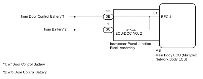
Based on changes in the power source voltage, the main body ECU (multiplex network body ECU) can detect if the battery has been disconnected and reconnected.
WIRING DIAGRAM
CAUTION / NOTICE / HINT
Note
-
Before replacing the main body ECU (multiplex network body ECU), refer to Service Bulletin.*
-
*: w/ Smart Entry and Start System
-
Inspect the fuses for circuits related to this system before performing the following procedure.
-
The vehicle battery supplies power to the main body ECU (multiplex network body ECU) via the door control battery. Therefore, before performing this troubleshooting procedure, make sure to perform an on-vehicle inspection to confirm that the main body ECU (multiplex network body ECU) power source circuit is normal.*
-
*: w/ Door Control Battery
PROCEDURE
-
CHECK HARNESS AND CONNECTOR (POWER SUPPLY)
-
Disconnect the 3B*1 or 3C*2 instrument panel junction block assembly connectors.
-
*1: w/ Door Control Battery
-
*2: w/o Door Control Battery
-
-
Measure the voltage according to the value(s) in the table below.
Standard Voltage w/ Door Control Battery Tester Connection Condition Specified Condition 3B-23 - Body ground Always 8.5 V or higher Standard Voltage w/o Door Control Battery Tester Connection Condition Specified Condition 3C-1 - Body ground Always 8.5 V or higher Result Proceed to OK NG
NG 
REPAIR OR REPLACE HARNESS OR CONNECTOR
OK 
-
-
INSPECT INSTRUMENT PANEL JUNCTION BLOCK ASSEMBLY
-
Remove the main body ECU (multiplex network body ECU).
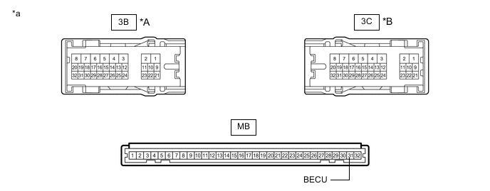
*A w/ Door Control Battery *B w/o Door Control Battery *a Component without harness connected
(Instrument Panel Junction Block Assembly)
- - -
Measure the resistance according to the value(s) in the table below.
Standard Resistance w/ Door Control Battery Tester Connection Condition Specified Condition 3B-23 - MB-31 (BECU) Always Below 1 Ω Standard Resistance w/o Door Control Battery Tester Connection Condition Specified Condition 3C-1 - MB-31 (BECU) Always Below 1 Ω Result Proceed to OK NG
OK
REPLACE MAIN BODY ECU (MULTIPLEX NETWORK BODY ECU) Click here
NG
REPLACE INSTRUMENT PANEL JUNCTION BLOCK ASSEMBLY Click here
-