WIRELESS DOOR LOCK CONTROL SYSTEM(w/ Smart Entry and Start System) TERMINALS OF ECU
-
CHECK INSTRUMENT PANEL JUNCTION BLOCK ASSEMBLY AND MAIN BODY ECU (MULTIPLEX NETWORK BODY ECU)
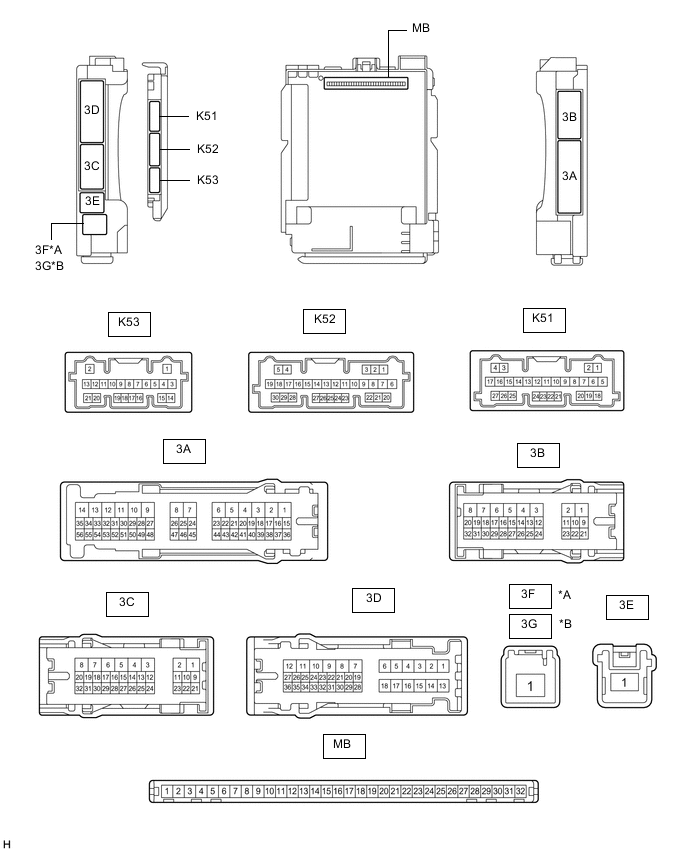
*A for LHD *B for RHD
-
Remove the main body ECU (multiplex network body ECU) from the instrument panel junction block assembly.
-
Reconnect the instrument panel junction block assembly connectors.
-
Measure the voltage and resistance according to the value(s) in the table below.
Terminal No. (Symbol) Wiring Color Input/Output Terminal Description Condition Specified Condition Related Data List Item MB-11 (GND1) - Body ground - - Ground Always Below 1 Ω - MB-30 (ACC) - Body ground - Input ACC power supply Engine switch on (ACC) 11 to 14 V ACC SW Engine switch off Below 1 V MB-31 (BECU) - Body ground - Input Battery power supply Always 11 to 14 V - MB-32 (IG) - Body ground - Input IG power supply Engine switch on (IG) 11 to 14 V IG SW Engine switch off Below 1 V -
Install the main body ECU (multiplex network body ECU) to the instrument panel junction block assembly.
-
Measure the voltage and check for pulses according to the value(s) in the table below.
Terminal No. (Symbol) Wiring Color Input/Output Terminal Description Condition Specified Condition Related Data List Item 3C-29 (BZR) - Body ground L - Body ground Output Wireless door lock buzzer output Active Test Wireless Buzzer is OFF Below 1 V - Active Test Wireless Buzzer is ON Pulse generation
(frequency: 2 kHz, high voltage: 11 to 14 V, low voltage: below 1 V)
-
-
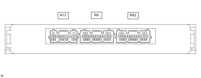
CHECK CERTIFICATION ECU (SMART KEY ECU ASSEMBLY)
-
Disconnect the K62 certification ECU (smart key ECU assembly) connector.
-
Measure the voltage and resistance according to the value(s) in the table below.
Terminal No. (Symbol) Wiring Color Input/Output Terminal Description Condition Specified Condition Related Data List Item K62-4 (+B) - Body ground W - Body ground Input Battery power supply Always 11 to 14 V - K62-18 (E) - Body ground W-B - Body ground - Ground Always Below 1 Ω - -
Reconnect the K62 certification ECU (smart key ECU assembly) connector.
-
Check for pulses according to the value(s) in the table below.
Terminal No. (Symbol) Wiring Color Input/Output Terminal Description Condition Specified Condition Related Data List Item R8-18 (RCO) - K62-18 (E) B - W-B Output Output to door control receiver
(Power supply for door control receiver. Certification ECU (smart key ECU assembly) outputs 5 V when receiver starts operating.)
-
Turn engine switch off
-
Bring electrical key transmitter sub-assembly outside detection area but within wireless function operational area
-
Press lock or unlock switch of electrical key transmitter sub-assembly
Procedure:
Plus generation (See waveform 1) - R8-19 (RDAM) - K62-18 (E) G - W-B Input Door control receiver communication circuit
-
Turn engine switch off
-
Lock all doors
-
Bring electrical key transmitter sub-assembly outside detection area but within wireless function operational area
-
Press lock or unlock switch of electrical key transmitter sub-assembly
Procedure:
Plus generation (See waveform 2) - R8-20 (CSEL) - K62-18 (E) BE - W-B Output Communication channel switching circuit
-
Turn engine switch off
-
Close all doors
Procedure:
No pulse generation → Pulse generation - -
-
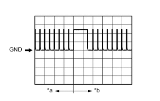
*a Before lock or unlock switch of electrical key transmitter sub-assembly pressed *b After lock or unlock switch of electrical key transmitter sub-assembly pressed Using an oscilloscope, check waveform 1.
Tech Tips
The oscilloscope waveform shown in the illustration is an example for reference only. Noise, chattering, etc. are not shown.
Waveform 1 (Reference) Item Content Tester connection R8-18 (RCO) - K62-18 (E) Tool setting 2 V/DIV., 500 ms/DIV. Condition Procedure:
-
Turn engine switch off
-
Bring electrical key transmitter sub-assembly outside detection area but within wireless function operational area
-
Press lock or unlock switch of electrical key transmitter sub-assembly
-
-
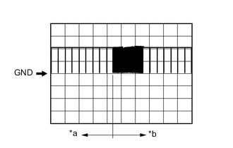
*a Before lock or unlock switch of electrical key transmitter sub-assembly pressed *b After lock or unlock switch of electrical key transmitter sub-assembly pressed Using an oscilloscope, check waveform 2.
Tech Tips
The oscilloscope waveform shown in the illustration is an example for reference only. Noise, chattering, etc. are not shown.
Waveform 2 (Reference) Item Content Tester connection R8-19 (RDAM) - K62-18 (E) Tool setting 5 V/DIV., 500 ms/DIV. Condition Procedure:
-
Turn engine switch off
-
Lock all doors
-
Bring electrical key transmitter sub-assembly outside detection area but within wireless function operational area
-
Press lock or unlock switch of electrical key transmitter sub-assembly
-
-