POWER DOOR LOCK CONTROL SYSTEM TERMINALS OF ECU
-
CHECK INSTRUMENT PANEL JUNCTION BLOCK ASSEMBLY AND MAIN BODY ECU (MULTIPLEX NETWORK BODY ECU)
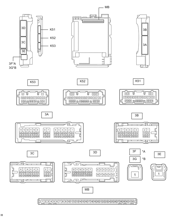
*A for LHD *B for RHD
-
Remove the main body ECU (multiplex network body ECU) from the instrument panel junction block assembly.
-
Reconnect the instrument panel junction block assembly connectors.
-
Measure the voltage and resistance according to the value(s) in the table below.
Terminal No. (Symbol) Wiring Color Input/Output Terminal Description Condition Specified Condition Related Data List Item MB-11 (GND1) - Body ground - - Ground Always Below 1 Ω - MB-30 (ACC) - Body ground - Input ACC power supply Ignition switch ACC 11 to 14 V ACC SW Ignition switch off Below 1 V MB-31 (BECU) - Body ground - Input Battery power supply Always 11 to 14 V - MB-32 (IG) - Body ground - Input IG power supply Ignition switch ON 11 to 14 V IG SW Ignition switch off Below 1 V -
Install the main body ECU (multiplex network body ECU) to the instrument panel junction block assembly.
-
Measure the voltage and check for pulses according to the value(s) in the table below.
Terminal No. (Symbol) Wiring Color Input/Output Terminal Description Condition Specified Condition Related Data List Item K52-1 (FLCY) - Body ground W- Body ground Input Front door courtesy light switch (for LH) input Front door LH open → closed Below 1 V → 11 to 14 V FL Door Courtesy SW K52-6 (FRCY) - Body ground BE - Body ground Input Front door courtesy light switch (for RH) input Front door RH open → closed Below 1 V → 11 to 14 V FR Door Courtesy SW 3D-24 (LCTY) - Body ground G - Body ground Input Rear door courtesy light switch (for LH) input Rear door LH open → closed Below 1 V → 11 to 14 V RL Door Courtesy SW 3A-31 (RCTY) - Body ground V - Body ground Input Rear door courtesy light switch (for RH) input Rear door RH open → closed Below 1 V → 11 to 14 V RR Door Courtesy SW 3B-13 (LSFL) - Body ground W - Body ground Input Front door LH unlock detection switch input Front door LH unlocked → locked Below 1 V → 11 to 14 V FL Door Lock Pos 3B-12 (LSFR) - Body ground GR - Body ground Input Front door RH unlock detection switch input Front door RH unlocked → locked Below 1 V → 11 to 14 V FR Door Lock Pos 3B-14 (LSWL) - Body ground GR - Body ground Input Rear door LH unlock detection switch input Rear door LH unlocked → locked Below 1 V → 11 to 14 V RL-Door Lock Pos SW K51-20 (LSWR) - Body ground L - Body ground Input Rear door RH unlock detection switch input Rear door RH unlocked → locked Below 1 V → 11 to 14 V RR-Door Lock Pos SW 3D-8 (ACT-) - Body ground LA-R - Body ground Output Door lock motor unlock drive output Door control switch or driver door key cylinder off → on (unlock) Below 1 V → 11 to 14 V → Below 1 V - 3D-9 (ACT-) - Body ground R - Body ground*1
LA-R - Body ground*2
Output Door lock motor unlock drive output Door control switch or driver door key cylinder off → on (unlock) Below 1 V → 11 to 14 V → Below 1 V - 3D-6 (ACT+) - Body ground LA-B - Body ground Output Door lock motor lock drive output Door control switch or driver door key cylinder off → on (lock) Below 1 V → 11 to 14 V → Below 1 V - 3D-18 (ACT+) - Body ground LA-B - Body ground Output Door lock motor lock drive output Door control switch or driver door key cylinder off → on (lock) Below 1 V → 11 to 14 V → Below 1 V - 3B-4 (ACTD) - Body ground*3 LA-L - Body ground Output Door lock motor unlock drive output Door control switch or driver door key cylinder off → on (unlock) Below 1 V → 11 to 14 V → Below 1 V - 3B-16 (L1) - Body ground*4 LG - Body ground Input Door control switch assembly input Door control switch assembly off → on (lock) Pulse generation → Below 1 V Door Lock SW-Lock 3A-39 (UL1) - Body ground*4 GR - Body ground Input Door control switch assembly input Door control switch assembly off → on (unlock) Pulse generation → Below 1 V Door Lock SW-Unlock K53-17 (UL3) - Body ground BE - Body ground Input Driver door key-linked unlock input Driver door key cylinder in neutral position → on (unlock) 11 to 14 V → Below 1 V D Door Key SW-UL K53-18 (L2) - Body ground LG - Body ground Input Driver door key-linked lock input Driver door key cylinder in neutral position → on (lock) 11 to 14 V → Below 1 V Door Key SW-Lock 3A-41 (KSW) - Body ground*5 GR - Body ground Input Key unlock warning switch input No key in ignition key cylinder → Key in ignition key cylinder 11 to 14 V → Below 1 V Key Unlock Warning SW 3A-7 (GSW) - Body ground B - Body ground Input Airbag sensor signal (collision detection signal) Ignition switch ON with airbag sensor assembly connector disconnected 4.3 to 5.5 V - K52-9 (ACTG) - Body ground*6 GR - Body ground Input Collision door lock release signal Collision door lock release function does not operate Below 2 V*7
7.3 to 9.9 V*8
- Collision door lock release function operates Below 1 V -
-
*1: for LHD
-
*2: for RHD
-
*3: w/ Key-linked 2-step Unlock Function
-
*4: w/ Canister Pump Module
-
*5: w/o Smart Entry and Start System
-
*6: w/ Door Control Battery
-
*7: Door control battery not charged
-
*8: Door control battery charging or charged
-
-
-
CHECK AIRBAG SENSOR ASSEMBLY