LIN COMMUNICATION SYSTEM TERMINALS OF ECU
-
CHECK INSTRUMENT PANEL JUNCTION BLOCK ASSEMBLY AND MAIN BODY ECU (MULTIPLEX NETWORK BODY ECU)
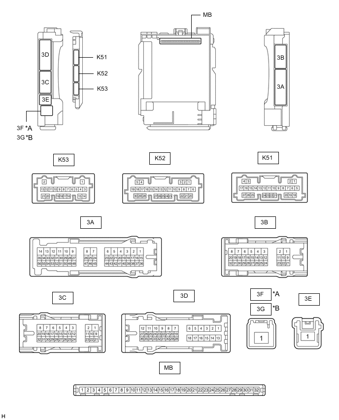
*A for LHD *B for RHD
-
Disconnect the MB main body ECU (multiplex network body ECU) connector.
-
Measure the voltage and resistance according to the value(s) in the table below.
Tech Tips
Measure the values on the wire harness side with the connectors disconnected.
Terminal No. (Symbol) Wiring Color Terminal Description Condition Specified Condition MB-11 (GND1) - Body ground - Ground Always Below 1 Ω MB-31 (BECU) - Body ground - Battery power supply Always 11 to 14 V MB-30 (ACC) - Body ground - ACC power supply Ignition switch ACC 11 to 14 V Ignition switch off Below 1 V MB-32 (IG) - Body ground - IG power supply Ignition switch ON 11 to 14 V Ignition switch off Below 1 V -
Reconnect the MB main body ECU (multiplex network body ECU) connector.
-
Check for pulses according to the value(s) in the table below.
Terminal No. (Symbol) Wiring Color Terminal Description Condition Specified Condition 3D-25 - Body ground LA-BE - Body ground LIN communication line Ignition switch ON Pulse generation 3B-17 - Body ground* L - Body ground LIN communication line Ignition switch ON Pulse generation
-
*: w/ Panoramic Moon Roof System or Sliding Roof System
-
-
-
CHECK POWER WINDOW REGULATOR MOTOR ASSEMBLY (DRIVER DOOR)

*A for LHD *B for RHD
-
Disconnect the O6*1 or N7*2 power window regulator motor assembly (driver door) connector.
-
*1: for LHD
-
*2: for RHD
-
-
Measure the voltage and resistance according to the value(s) in the table below.
Tech Tips
Measure the values on the wire harness side with the connector disconnected.
for LHD Terminal No. (Symbol) Wiring Color Terminal Description Condition Specified Condition O6-2 (B) - Body ground GR - Body ground Battery power supply Always 11 to 14 V O6-1 (GND) - Body ground W-B - Body ground Ground Always Below 1 Ω for RHD Terminal No. (Symbol) Wiring Color Terminal Description Condition Specified Condition N7-2 (B) - Body ground GR - Body ground Battery power supply Always 11 to 14 V N7-1 (GND) - Body ground W-B - Body ground Ground Always Below 1 Ω -
Reconnect the O6*1 or N7*2 power window regulator motor assembly (driver door) connector.
-
*1: for LHD
-
*2: for RHD
-
-
Check for pulses according to the value(s) in the table below.
for LHD Terminal No. (Symbol) Wiring Color Terminal Description Condition Specified Condition O6-9 (LIN) - Body ground G - Body ground LIN communication line Ignition switch ON Pulse generation for RHD Terminal No. (Symbol) Wiring Color Terminal Description Condition Specified Condition N7-9 (LIN) - Body ground G - Body ground LIN communication line Ignition switch ON Pulse generation
-
-
CHECK POWER WINDOW REGULATOR MOTOR ASSEMBLY (FRONT PASSENGER DOOR)

*A for LHD *B for RHD
-
Disconnect the N7*1 or O6*2 power window regulator motor assembly (front passenger door) connector.
-
*1: for LHD
-
*2: for RHD
-
-
Measure the voltage and resistance according to the value(s) in the table below.
Tech Tips
Measure the values on the wire harness side with the connector disconnected.
for LHD Terminal No. (Symbol) Wiring Color Terminal Description Condition Specified Condition N7-2 (B) - Body ground GR - Body ground Battery power supply Always 11 to 14 V N7-1 (GND) - Body ground W-B - Body ground Ground Always Below 1 Ω for RHD Terminal No. (Symbol) Wiring Color Terminal Description Condition Specified Condition O6-2 (B) - Body ground GR - Body ground Battery power supply Always 11 to 14 V O6-1 (GND) - Body ground W-B - Body ground Ground Always Below 1 Ω -
Reconnect the N7*1 or O6*2 power window regulator motor assembly (front passenger door) connector.
-
*1: for LHD
-
*2: for RHD
-
-
Check for pulses according to the value(s) in the table below.
for LHD Terminal No. (Symbol) Wiring Color Terminal Description Condition Specified Condition N7-9 (LIN) - Body ground P - Body ground LIN communication line Ignition switch ON Pulse generation for RHD Terminal No. (Symbol) Wiring Color Terminal Description Condition Specified Condition O6-9 (LIN) - Body ground P - Body ground LIN communication line Ignition switch ON Pulse generation
-
-
CHECK POWER WINDOW REGULATOR MOTOR ASSEMBLY (REAR RH DOOR)

-
Disconnect the P6 power window regulator motor assembly (rear RH door) connector.
-
Measure the voltage and resistance according to the value(s) in the table below.
Tech Tips
Measure the values on the wire harness side with the connector disconnected.
Terminal No. (Symbol) Wiring Color Terminal Description Condition Specified Condition P6-2 (B) - Body ground B - Body ground Battery power supply Always 11 to 14 V P6-1 (GND) - Body ground W-B - Body ground Ground Always Below 1 Ω -
Reconnect the P6 power window regulator motor assembly (rear RH door) connector.
-
Check for pulses according to the value(s) in the table below.
Terminal No. (Symbol) Wiring Color Terminal Description Condition Specified Condition P6-9 (LIN) - Body ground P - Body ground LIN communication line Ignition switch ON Pulse generation
-
-
CHECK POWER WINDOW REGULATOR MOTOR ASSEMBLY (REAR LH DOOR)

-
Disconnect the Q6 power window regulator motor assembly (rear LH door) connector.
-
Measure the voltage and resistance according to the value(s) in the table below.
Tech Tips
Measure the values on the wire harness side with the connector disconnected.
Terminal No. (Symbol) Wiring Color Terminal Description Condition Specified Condition Q6-2 (B) - Body ground B - Body ground Battery power supply Always 11 to 14 V Q6-1 (GND) - Body ground W-B - Body ground Ground Always Below 1 Ω -
Reconnect the Q6 power window regulator motor assembly (rear LH door) connector.
-
Check for pulses according to the value(s) in the table below.
Terminal No. (Symbol) Wiring Color Terminal Description Condition Specified Condition Q6-9 (LIN) - Body ground P - Body ground LIN communication line Ignition switch ON Pulse generation
-
-
CHECK MULTIPLEX NETWORK MASTER SWITCH ASSEMBLY

*A for LHD *B for RHD
-
Disconnect the O2*1 or N2*2 multiplex network master switch assembly connector.
-
*1: for LHD
-
*2: for RHD
-
-
Measure the voltage and resistance according to the value(s) in the table below.
Tech Tips
Measure the values on the wire harness side with the connector disconnected.
for LHD Terminal No. (Symbol) Wiring Color Terminal Description Condition Specified Condition O2-11 (B) - Body ground LA-R - Body ground Battery power supply Always 11 to 14 V O2-12 (GND) - Body ground W-B - Body ground Ground Always Below 1 Ω for RHD Terminal No. (Symbol) Wiring Color Terminal Description Condition Specified Condition N2-11 (B) - Body ground LA-R - Body ground Battery power supply Always 11 to 14 V N2-12 (GND) - Body ground W-B - Body ground Ground Always Below 1 Ω -
Reconnect the O2*1 or N2*2 multiplex network master switch assembly connector.
-
*1: for LHD
-
*2: for RHD
-
-
Check for pulses according to the value(s) in the table below.
for LHD Terminal No. (Symbol) Wiring Color Terminal Description Condition Specified Condition O2-17 (LIN1) - Body ground P - Body ground LIN communication line Ignition switch ON Pulse generation O2-16 (LIN2) - Body ground G - Body ground LIN communication line Ignition switch ON Pulse generation for RHD Terminal No. (Symbol) Wiring Color Terminal Description Condition Specified Condition N2-17 (LIN1) - Body ground P - Body ground LIN communication line Ignition switch ON Pulse generation N2-16 (LIN2) - Body ground G - Body ground LIN communication line Ignition switch ON Pulse generation
-
-
CHECK SLIDING ROOF ECU (SLIDING ROOF DRIVE GEAR ASSEMBLY) (w/ Panoramic Moon Roof System)

-
Disconnect the q1 sliding roof ECU (sliding roof drive gear assembly) connector.
-
Measure the voltage and resistance according to the value(s) in the table below.
Tech Tips
Measure the values on the wire harness side with the connector disconnected.
Terminal No. (Symbol) Wiring Color Terminal Description Condition Specified Condition q1-1 (+B) - Body ground L - Body ground Battery power supply Always 11 to 14 V q1-2 (E) - Body ground W-B - Body ground Ground Always Below 1 Ω -
Reconnect the q1 sliding roof ECU (sliding roof drive gear assembly) connector.
-
Check for pulses according to the value(s) in the table below.
Terminal No. (Symbol) Wiring Color Terminal Description Condition Specified Condition q1-7 (LIN) - Body ground B - Body ground LIN communication line Ignition switch ON Pulse generation
-
-
CHECK ROOF SUNSHADE ECU (SLIDING ROOF DRIVE GEAR ASSEMBLY) (w/ Panoramic Moon Roof System)

-
Disconnect the q2 roof sunshade ECU (sliding roof drive gear assembly) connector.
-
Measure the voltage and resistance according to the value(s) in the table below.
Tech Tips
Measure the values on the wire harness side with the connector disconnected.
Terminal No. (Symbol) Wiring Color Terminal Description Condition Specified Condition q2-1 (+B) - Body ground G - Body ground Battery power supply Always 11 to 14 V q2-2 (E) - Body ground W-B - Body ground Ground Always Below 1 Ω -
Reconnect the q2 roof sunshade ECU (sliding roof drive gear assembly) connector.
-
Check for pulses according to the value(s) in the table below.
Terminal No. (Symbol) Wiring Color Terminal Description Condition Specified Condition q2-7 (LIN) - Body ground B - Body ground LIN communication line Ignition switch ON Pulse generation
-
-
CHECK SLIDING ROOF ECU (SLIDING ROOF DRIVE GEAR SUB-ASSEMBLY) (w/ Sliding Roof System)

-
Disconnect the V19 sliding roof ECU (sliding roof drive gear sub-assembly) connector.
-
Measure the voltage and resistance according to the value(s) in the table below.
Tech Tips
Measure the values on the wire harness side with the connector disconnected.
Terminal No. (Symbol) Wiring Color Terminal Description Condition Specified Condition V19-1 (B) - Body ground B - Body ground Battery power supply Always 11 to 14 V V19-2 (E) - Body ground W-B - Body ground Ground Always Below 1 Ω -
Reconnect the V19 sliding roof ECU (sliding roof drive gear sub-assembly) connector.
-
Check for pulses according to the value(s) in the table below.
Terminal No. (Symbol) Wiring Color Terminal Description Condition Specified Condition V19-7 (MPX1) - Body ground LA-P - Body ground LIN communication line Ignition switch ON Pulse generation
-
-
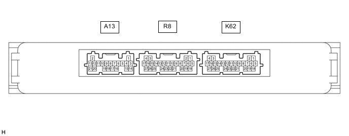
CHECK CERTIFICATION ECU (SMART KEY ECU ASSEMBLY) (w/ Smart Entry and Start System)
-
Disconnect the K62 certification ECU (smart key ECU assembly) connector.
-
Measure the voltage and resistance according to the value(s) in the table below.
Tech Tips
Measure the values on the wire harness side with the connector disconnected.
Terminal No. (Symbol) Wiring Color Terminal Description Condition Specified Condition K62-4 (+B) - Body ground W - Body ground Battery power supply Always 11 to 14 V K62-18 (E) - Body ground W-B - Body ground Ground Always Below 1 Ω -
Reconnect the K62 certification ECU (smart key ECU assembly) connector.
-
Check for pulses according to the value(s) in the table below.
Terminal No. (Symbol) Wiring Color Terminal Description Condition Specified Condition K62-13 (LIN) - Body ground B - Body ground LIN communication line Ignition switch ON Pulse generation
-
-
CHECK STEERING LOCK ECU (STEERING LOCK ACTUATOR OR UPPER BRACKET ASSEMBLY) (w/ Smart Entry and Start System)

-
Disconnect the K65 steering lock ECU (steering lock actuator or upper bracket assembly) connector.
-
Measure the voltage and resistance according to the value(s) in the table below.
Terminal No. (Symbol) Wiring Color Terminal Description Condition Specified Condition K65-7 (B) - Body ground W - Body ground Battery power supply Always 11 to 14 V K65-1 (GND) - Body ground W-B - Body ground Ground Always Below 1 Ω -
Reconnect the K65 steering lock ECU (steering lock actuator or upper bracket assembly) connector.
-
Check for pulses according to the value(s) in the table below.
Terminal No. (Symbol) Wiring Color Terminal Description Condition Specified Condition K65-5 (LIN) - Body ground B - Body ground LIN communication line Ignition switch ON Pulse generation
-
-
CHECK ID CODE BOX (IMMOBILISER CODE ECU) (w/ ID Code Box)

-
Disconnect the K139 ID code box (immobiliser code ECU) connector.
-
Measure the voltage and resistance according to the value(s) in the table below.
Tech Tips
Measure the values on the wire harness side with the connector disconnected.
Terminal No. (Symbol) Wiring Color Terminal Description Condition Specified Condition K139-5 (GND) - Body ground W-B - Body ground Ground Always Below 1 Ω K139-1 (+B) - Body ground LA-GR - Body ground +B power supply Always 11 to 14 V -
Reconnect the K139 ID code box (immobiliser code ECU) connector.
-
Check for pulses according to the value(s) in the table below.
Terminal No. (Symbol) Wiring Color Terminal Description Condition Specified Condition K139-2 (LIN) - Body ground GR - Body ground LIN communication line Ignition switch ON Pulse generation
-