ABSORBER CONTROL ACTUATOR(for Rear Side) INSTALLATION
PROCEDURE
-
INSTALL ABSORBER CONTROL ACTUATOR
Tech Tips
-
Use the same procedure for the RH side and LH side.
-
The following procedure is for the LH side.
-
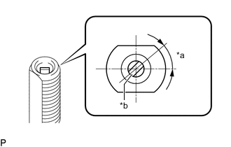
*a 40° *b Control Rod Check that the control rod of the rear shock absorber assembly is in the position shown in the illustration.
Note
If the control rod is not in the position shown in the illustration, turn the control rod to adjust the position before installing the absorber control actuator.
-

*a Absorber Control Actuator Output Shaft *b Control Rod Install the absorber control actuator to the rear actuator support bracket.
Note
Make sure to check that the absorber control actuator output shaft and control rod are securely connected.
-
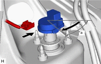
*a 40° Turn the absorber control actuator 40° clockwise until a click is felt.
Note
-
Before turning the absorber control actuator, make sure to check that the absorber control actuator output shaft and control rod are securely connected.
-
Do not turn the absorber control actuator more than 40°.
-
Do not drop the absorber control actuator. If it is dropped, replace it with a new one.
-
-
Connect the connector.
-
Return the luggage compartment trim cover to its original position.
-
-
INSTALL LUGGAGE COMPARTMENT TRIM COVER LH (for LH Side)
-
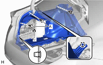
Engage the claw.
-
Install the luggage compartment trim cover LH with the 2 clips (A) and clip (B).
-
Install a new clip (C).
-
Install the 2 rope hook assemblies with the 2 bolts.
-
Engage the 4 claws to close the 2 covers.
-
-
INSTALL LUGGAGE COMPARTMENT TRIM COVER RH (for RH Side)
-
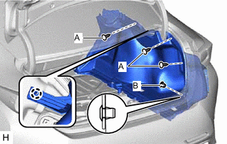
Engage the claw.
-
Install the luggage compartment trim cover RH with the 3 clips (A).
-
Install a new clip (B).
-
Install the 2 rope hook assemblies with the 2 bolts.
-
Engage the 4 claws to close the 2 covers.
-
-
INSTALL FRONT UPPER LUGGAGE COMPARTMENT TRIM COVER
-
INSTALL NO. 1 LUGGAGE COMPARTMENT LIGHT ASSEMBLY
-
INSTALL FRONT LUGGAGE COMPARTMENT TRIM COVER
-
INSTALL REAR LUGGAGE COMPARTMENT TRIM COVER
-
INSTALL LUGGAGE COMPARTMENT TRIM BOX
-
INSTALL NO. 1 LUGGAGE COMPARTMENT TRIM COVER
-
CONNECT CABLE TO NEGATIVE AUXILIARY BATTERY TERMINAL
Note
When disconnecting the cable from the negative (-) auxiliary battery terminal, some systems need to be initialized after the cable is reconnected.
-
INSTALL BATTERY SERVICE HOLE COVER LH