FRONT DOOR REASSEMBLY

CAUTION / NOTICE / HINT
Tech Tips
-
Use the same procedure for both the RH side and LH side.
-
The following procedure is for the LH side.
PROCEDURE
-
PRECAUTION
Note
After turning the power switch off, waiting time may be required before disconnecting the cable from the negative (-) auxiliary battery terminal. Therefore, make sure to read the disconnecting the cable from the negative (-) auxiliary battery terminal notices before proceeding with work.
-
INSTALL FRONT DOOR BELT MOULDING
-
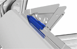
INSTALL FRONT DOOR FRONT LOWER FRAME UPPER COVER
-
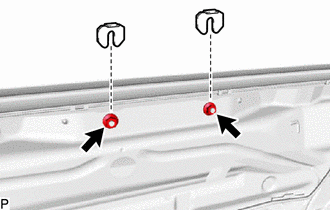
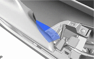
INSTALL FRONT DOOR PANEL CUSHION
-
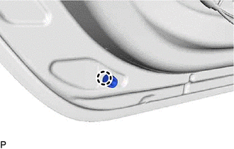
Engage the claw to install a new front door panel cushion.
-
-
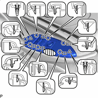
INSTALL FRONT DOOR NO. 2 WEATHERSTRIP
-
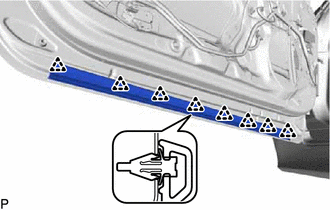
Engage the 8 clips to install the front door No. 2 weatherstrip.
-
-
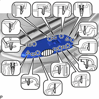
INSTALL FRONT DOOR WEATHERSTRIP
-
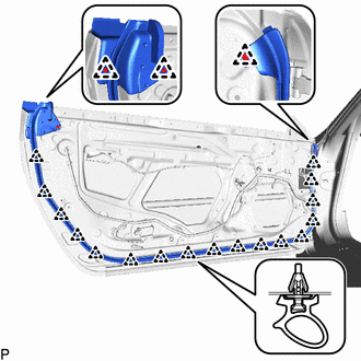
Engage the 20 clips to install the front door weatherstrip.
-
-
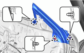
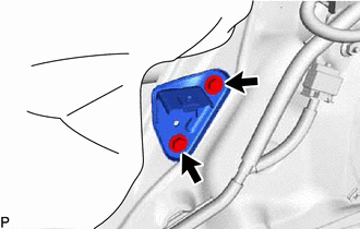
INSTALL FRONT DOOR CHECK ASSEMBLY
-
Apply MP grease to the sliding areas of the front door check assembly.
-
Clean the bolt hole on the vehicle body.
-
Clean the threads of the bolt.
-
Apply adhesive to the threads of the bolt.
Adhesive Toyota Genuine Adhesive 1324, Three Bond 1324 or equivalent -
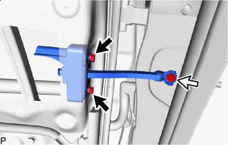

Nut 
Bolt Install the front door check assembly with the 2 nuts and bolt.
- Torque:
- Nut
- 8.0 N*m { 82 kgf*cm, 71 in.*lbf }
- Bolt
- 27 N*m { 275 kgf*cm, 20 ft.*lbf }
-
-
INSTALL FRONT DOOR VENT SEAL
-
Install the front door vent seal.
-
-
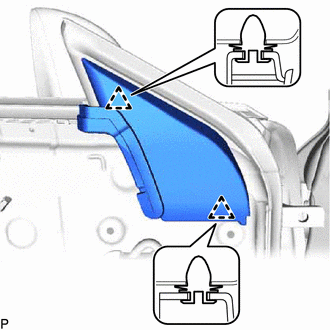
INSTALL FRONT DOOR DIVISION BAR SEAL
-
Engage the claw.
-
Engage the 2 clips to install the front door division bar seal.
-
-
INSTALL DOOR GLASS FEMALE STABILIZER
-
Engage the 2 guides.
-
Install the door glass female stabilizer with the bolt.
- Torque:
- 11.5 N*m { 117 kgf*cm, 8 ft.*lbf }
-
-
INSTALL FRONT DOOR LOCK OPEN ROD
-
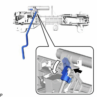
Install the front door lock open rod as indicated by the arrows, in the order shown in the illustration.
-
-
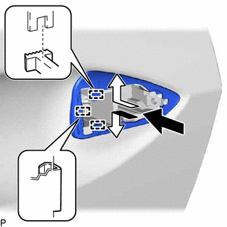
INSTALL FRONT DOOR OUTSIDE HANDLE FRAME SUB-ASSEMBLY
-
Apply MP grease to the sliding parts of the front door outside handle frame sub-assembly.
-
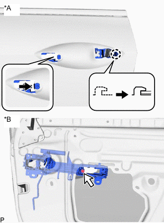
*A Outside *B Inside Engage the claw.
-
Using a T30 "TORX" socket wrench, install the front door outside handle frame sub-assembly with the screw.
- Torque:
- 4.0 N*m { 41 kgf*cm, 35 in.*lbf }
-
Engage the 3 clamps.
-
-
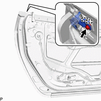
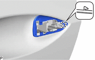
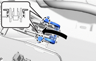
INSTALL FRONT DOOR LOCK WITH MOTOR ASSEMBLY
Note
-
When reusing a removed front door lock with motor assembly, replace the door lock wire harness seal with a new one.
-
Do not allow grease or dust to adhere to the door lock wire harness seal installation surface.
-
Reusing a door lock wire harness seal or using a damaged door lock wire harness seal may cause water ingress. This may result in a malfunction of the front door lock with motor assembly.
-
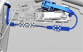
Apply MP grease to the sliding parts of the front door lock with motor assembly.
-
When reusing the front door lock with motor assembly:
-
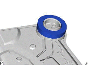
Install a new door lock wire harness seal to the front door lock with motor assembly.
-
-
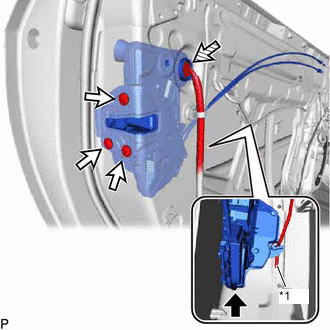
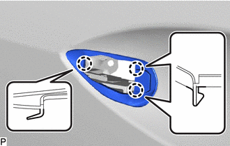
*1 Front Door Lock Open Rod Connect the front door lock open rod to the front door lock with motor assembly.
Tech Tips
Make sure that the front door lock open rod is securely connected to the front door lock with motor assembly.
-
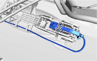
Using a T30 "TORX" socket wrench, install the front door lock with motor assembly with the 3 screws.
- Torque:
- 5.5 N*m { 56 kgf*cm, 49 in.*lbf }
-
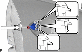
Connect the connector.
-
-
INSTALL FRONT DOOR REAR OUTSIDE HANDLE PAD
-
Engage the 3 guides as shown in the illustration.
-
Engage the claw to install the front door rear outside handle pad.
-
-
INSTALL FRONT DOOR OUTSIDE HANDLE PAD
-
Engage the 3 claws to install the front door outside handle pad.
-
-
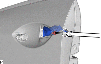
INSTALL FRONT DOOR OUTSIDE HANDLE COVER (for Front Passenger Side)
-
Engage the 2 guides and claw.
-
Using a T30 "TORX" socket wrench, install the front door outside handle cover with the screw.
- Torque:
- 4.0 N*m { 41 kgf*cm, 35 in.*lbf }
-
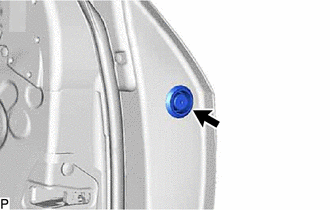
Install the hole plug.
-
-
INSTALL FRONT DOOR LOCK CYLINDER ASSEMBLY (for Driver Side)
-
Using a T30 "TORX" socket wrench, install the front door lock cylinder assembly with the screw.
- Torque:
- 4.0 N*m { 41 kgf*cm, 35 in.*lbf }
-
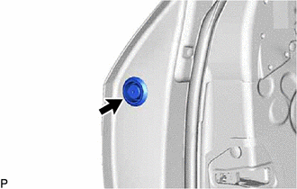
Install the hole plug.
-
-
INSTALL FRONT DOOR OUTSIDE HANDLE ASSEMBLY
-
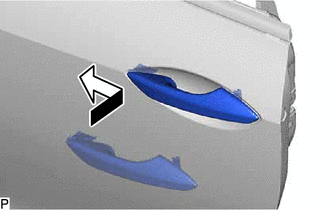
Insert the front end of the front door outside handle assembly into the front door outside handle frame sub-assembly.
-
Insert the rear end of the front door outside handle assembly into the front door outside handle frame sub-assembly, then slide the front door outside handle assembly toward the front of the vehicle to install it.
-
Move the lever as shown in the illustration and engage the 2 claws to lock the front door outside handle assembly.
-
Connect the connector.
-
Engage the 2 claws.
-
-
INSTALL FRONT DOOR GLASS RUN
-
Engage the guide to install the front door glass run.
-
-
INSTALL FRONT DOOR WINDOW REGULATOR ASSEMBLY
-
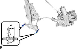
Using a 4 mm hexagon wrench, adjust the 2 stud bolts at the bottom of the front door window regulator assembly as shown in the illustration.
Standard Clearance A 21.1 to 22.1 mm (0.831 to 0.870 in.) -
Apply MP grease to the sliding parts of the front door window regulator assembly.
-
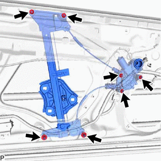
Temporarily install the front door window regulator assembly with the 7 nuts.
-
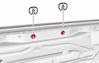
Install the 2 window regulator shims.
-
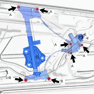
Tighten the 7 nuts to install the front door window regulator assembly.
- Torque:
- Nut (A)
- 5.5 N*m { 56 kgf*cm, 49 in.*lbf }
- Nut (B)
- 13 N*m { 133 kgf*cm, 10 ft.*lbf }
-
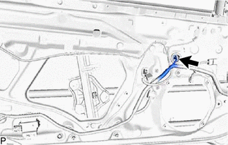
Connect the connector.
-
-
INSTALL FRONT DOOR GLASS SUB-ASSEMBLY
-
Connect the cable to the negative (-) auxiliary battery terminal.
-
for Driver Side:
-
Connect the multiplex network master switch assembly and move the front door window regulator assembly so that the door glass stud bolts can be seen.
-
-
for Front Passenger Side:
-
Connect the power window regulator switch assembly and move the front door window regulator assembly so that the door glass stud bolts can be seen.
-
-
Disconnect the cable from the negative (-) auxiliary battery terminal.
-
for Driver Side:
-
Disconnect the multiplex network master switch assembly.
-
-
for Front Passenger Side:
-
Disconnect the power window regulator switch assembly.
-
-
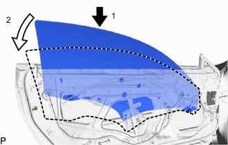
Insert the front door glass sub-assembly into the front door panel along the front door glass run as indicated by the arrows, in the order shown in the illustration.
-
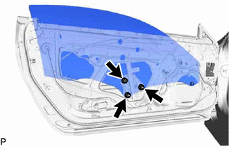
Install the front door glass sub-assembly with the 3 nuts.
- Torque:
- 8.0 N*m { 82 kgf*cm, 71 in.*lbf }
-
-
INSTALL FRONT DOOR UPPER WINDOW STOP
-
for Front Side:
-
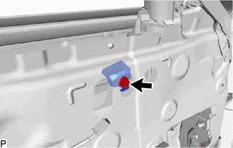
Install the front door upper window stop with the bolt.
- Torque:
- 11.5 N*m { 117 kgf*cm, 8 ft.*lbf }
-
-
for Rear Side:
-
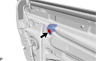
Install the front door upper window stop with the bolt.
- Torque:
- 11.5 N*m { 117 kgf*cm, 8 ft.*lbf }
-
-
-
INSPECT FRONT DOOR GLASS SUB-ASSEMBLY
-
Connect the cable to the negative (-) auxiliary battery terminal.
-
for Driver Side:
-
Connect the multiplex network master switch assembly and fully close the front door glass sub-assembly.
-
-
for Front Passenger Side:
-
Connect the power window regulator switch assembly and fully close the front door glass sub-assembly.
-
-
Check that the clearance measurements of areas a through m are within each standard range.
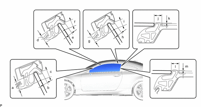
Standard Clearance Area Measurement Area Measurement a 15.0 mm (0.591 in.) b 5.6 to 9.6 mm (0.220 to 0.378 in.) c 9.1 to 13.1 mm (0.358 to 0.516 in.) d 15.0 mm (0.591 in.) e 5.7 to 9.7 mm (0.224 to 0.382 in.) f 9.1 to 13.1 mm (0.358 to 0.516 in.) g 15.0 mm (0.591 in.) h 5.7 to 9.7 mm (0.224 to 0.382 in.) i 9.1 to 13.1 mm (0.358 to 0.516 in.) j 12.0 mm (0.472 in.) k 0 mm (0 in.) l 12.0 mm (0.472 in.) m 0 mm (0 in.) - - Note
Be careful not to cut the weatherstrip during door glass adjustment.
-
-
ADJUST FRONT DOOR GLASS SUB-ASSEMBLY
-

Adjust the fit of the top part of the front door glass sub-assembly inward and outward.
-
Loosen the 2 nuts at the bottom of the front door window regulator assembly.
-
Using a 4 mm hexagon wrench, turn the 2 stud bolts to adjust the fit of the top part of the front door glass sub-assembly inward and outward.
Tech Tips
When the stud bolt are turned counterclockwise, the top part of the front door glass sub-assembly moves toward the inside of the vehicle. When the stud bolt are turned clockwise, the top part of the front door glass sub-assembly moves toward the outside of the vehicle.
-
Tighten the 2 nuts after adjustment.
- Torque:
- 13 N*m { 133 kgf*cm, 10 ft.*lbf }
-
-
Adjust the fit of the bottom part of the front door glass sub-assembly inward and outward.
-
Loosen the 2 nuts at the top of the front door window regulator assembly.
-
Change the number of installed window regulator shims to adjust the fit of the bottom part of the front door glass sub-assembly inward and outward.
Tech Tips
When more shims are used, the bottom part of the front door glass sub-assembly moves toward the outside of the vehicle. When less shims are used, the bottom part of the front door glass sub-assembly moves toward the inside of the vehicle.
-
Tighten the 2 nuts after adjustment.
- Torque:
- 5.5 N*m { 56 kgf*cm, 49 in.*lbf }
-
-
Adjust the front door glass sub-assembly fully closed position horizontally and vertically.
-
Loosen the 2 front door upper window stop bolts and temporarily move the front door upper window stops to the top of their adjustment range and then temporarily tighten the bolts.
-
Loosen the 3 front door glass sub-assembly nuts.
-
Stop the front door glass sub-assembly approximately 3 mm (0.118 in.) below the fully closed position.
-
While holding the front door glass sub-assembly, move it vertically and horizontally to adjust its position.
-
Tighten the 3 nuts after adjustment.
- Torque:
- 5.5 N*m { 56 kgf*cm, 49 in.*lbf }
-
Move the front door glass sub-assembly to the fully closed position.
-
Loosen the 2 front door upper window stop bolts.
-
While lightly pushing each front door upper window stop against the stopper on the front door glass sub-assembly, tighten each bolt.
- Torque:
- 11.5 N*m { 117 kgf*cm, 102 in.*lbf }
-
-
for Driver Side:
-
Disconnect the multiplex network master switch assembly.
-
-
for Front Passenger Side:
-
Disconnect the power window regulator switch assembly.
-
-
Disconnect the cable from the negative (-) auxiliary battery terminal.
-
-
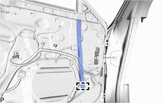
INSTALL FRONT DOOR SERVICE HOLE COVER
-
Apply new butyl tape to the front door panel.
-
Pass the front door lock remote control cable assembly and front door inside locking cable assembly through a new front door service hole cover.
-
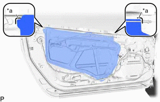
*a Reference Point Install the front door service hole cover according to the reference points on the front door panel.
Note
Securely install the front door service hole cover preventing wrinkles and air bubbles.
-
-
INSTALL FRONT NO. 1 SPEAKER ASSEMBLY
-
INSTALL FRONT DOOR TRIM BRACKET
-
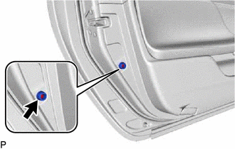
Install the front door trim bracket with the 2 screws.
-
-
INSTALL FRONT DOOR LOWER FRAME BRACKET GARNISH
-
Engage the 2 clips to install the front door lower frame bracket garnish.
-
-
INSTALL OUTER REAR VIEW MIRROR ASSEMBLY
-
INSTALL OUTER MIRROR PROTECTOR
-
INSTALL OUTER MIRROR INSTALL HOLE COVER
-
INSTALL OUTER MIRROR CONTROL ECU ASSEMBLY (w/ Memory)
-
INSTALL DOOR SIDE AIRBAG SENSOR
-
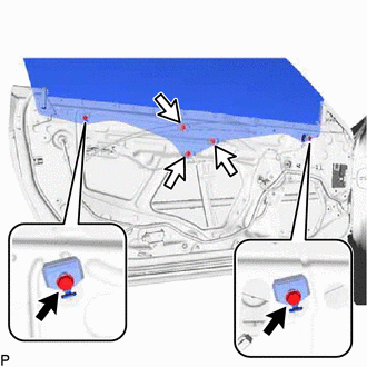
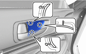
INSTALL FRONT DOOR INNER GLASS WEATHERSTRIP
-
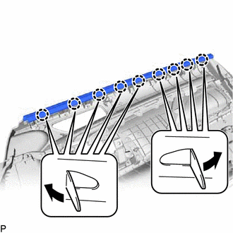
Engage the 9 claws to install the front door inner glass weatherstrip as shown in the illustration.
-
-
INSTALL SEAT MEMORY SWITCH (w/ Memory)
-
INSTALL FRONT DOOR INSIDE HANDLE SUB-ASSEMBLY
-
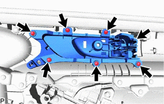
Install the front door inside handle sub-assembly with the 7 screws.
-
-
INSTALL NO. 1 INTERIOR ILLUMINATION LIGHT ASSEMBLY
-
INSTALL FRONT DOOR TRIM BOARD SUB-ASSEMBLY
-
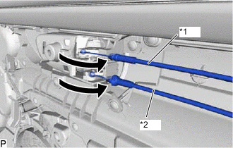
*1 Front Door Inside Locking Cable Assembly *2 Front Door Lock Remote Control Cable Assembly Connect the front door lock remote control cable assembly and front door inside locking cable assembly.
-
Connect each connector.
-
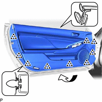
Engage the 9 clips to install the front door trim board sub-assembly as shown in the illustration.
-
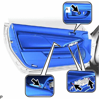
Install the 4 screws.
- Torque:
- Screw (A)
- 3.5 N*m { 36 kgf*cm, 31 in.*lbf }
-
-
INSTALL FRONT DOOR NO. 1 STIFFENER CUSHION
-
Install the front door No. 1 stiffener cushion with the screw.
-
-
INSTALL COURTESY LIGHT ASSEMBLY
-
INSTALL DOOR TRIM COVER
-
Install the door trim cover.
-
-
INSTALL MULTIPLEX NETWORK MASTER SWITCH ASSEMBLY WITH FRONT DOOR ARMREST BASE PANEL (for Driver Side)
-
Connect the connector.
-

Push Area Engage the 2 clips, 7 claws and 5 guides to install the multiplex network master switch assembly with front door armrest base panel.
-
Press the push area.
Tech Tips
Check that the front door armrest base panel are attached to the front door trim board sub-assembly correctly.
-
-
INSTALL POWER WINDOW REGULATOR SWITCH ASSEMBLY WITH FRONT DOOR ARMREST BASE PANEL (for Front Passenger Side)
-
Connect the connector.
-
Push Area Engage the 2 clips, 7 claws and 5 guides to install the power window regulator switch assembly with front door armrest base panel.
-
Press the push area.
Tech Tips
Check that the front door armrest base panel are attached to the front door trim board sub-assembly correctly.
-
-
INSTALL FRONT DOOR INSIDE HANDLE BEZEL PLUG
-
Engage the 3 claws to install the front door inside handle bezel plug.
-
-
CONNECT CABLE TO NEGATIVE AUXILIARY BATTERY TERMINAL
Note
When disconnecting the cable, some systems need to be initialized after the cable is reconnected.
-
INSTALL BATTERY SERVICE HOLE COVER LH
-
INITIALIZE POWER WINDOW CONTROL SYSTEM
-
INSPECT POWER WINDOW OPERATION
-
INSPECT SRS WARNING LIGHT