REAR NO. 1 SEAT OUTER BELT ASSEMBLY INSTALLATION

CAUTION / NOTICE / HINT
Tech Tips
-
Use the same procedure for the RH side and LH side.
-
The following procedure is for the LH side.
PROCEDURE
-
INSPECT REAR NO. 1 SEAT OUTER BELT ASSEMBLY
-
INSTALL REAR NO. 1 SEAT OUTER BELT ASSEMBLY LH
-
Engage the 2 guides.
-
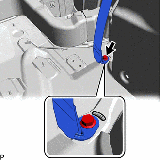
Install the rear No. 1 seat outer belt assembly LH to the outer belt anchor bracket sub-assembly LH with the nut.
- Torque:
- 42 N*m { 428 kgf*cm, 31 ft.*lbf }
-
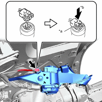
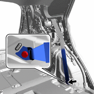
*a Locking Button *b Lock Connect the pretensioner connector and lock the locking button as shown in the illustration.
Note
Securely lock the locking button.
-
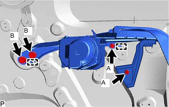
Engage the 2 guides and temporarily install the rear No. 1 seat outer belt assembly LH with the 4 bolts.
-
Fully tighten the 2 bolts (A) and then the 2 bolts (B) to install the rear No. 1 seat outer belt assembly LH.
- Torque:
- Bolt (A)
- 12.5 N*m { 127 kgf*cm, 9 ft.*lbf }
- Bolt (B)
- 42 N*m { 428 kgf*cm, 31 ft.*lbf }
-
Check that the ELR locks.
Note
This check should be performed with the rear No. 1 seat outer belt assembly LH installed to the vehicle.
-
With the rear No. 1 seat outer belt assembly LH installed to the vehicle, check that the belt locks when it is pulled out quickly.
-
-
-
INSTALL REAR NO. 1 SEAT OUTER BELT ASSEMBLY RH
-
Engage the 2 guides.
-
Install the rear No. 1 seat outer belt assembly RH to the outer belt anchor bracket sub-assembly RH with the nut.
- Torque:
- 42 N*m { 428 kgf*cm, 31 ft.*lbf }
-
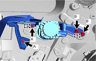
Engage the 2 guides and temporarily install the rear No. 1 seat outer belt assembly RH with the 4 bolts.
-
Fully tighten the 2 bolts (A) and then the 2 bolts (B) to install the rear No. 1 seat outer belt assembly RH.
- Torque:
- Bolt (A)
- 12.5 N*m { 127 kgf*cm, 9 ft.*lbf }
- Bolt (B)
- 42 N*m { 428 kgf*cm, 31 ft.*lbf }
-
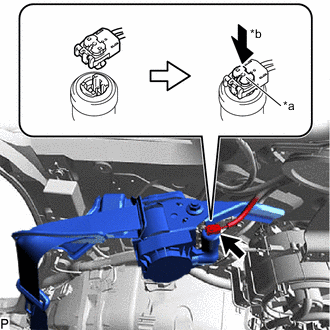
*a Locking Button *b Lock Connect the pretensioner connector and lock the locking button as shown in the illustration.
Note
Securely lock the locking button.
-
Check that the ELR locks.
Note
This check should be performed with the rear No. 1 seat outer belt assembly RH installed to the vehicle.
-
With the rear No. 1 seat outer belt assembly RH installed to the vehicle, check that the belt locks when it is pulled out quickly.
-
-
-
CONNECT REAR NO. 1 SEAT OUTER BELT ASSEMBLY
-

Protruding Part Connect the floor anchor of the rear No. 1 seat outer belt assembly with the bolt.
- Torque:
- 42 N*m { 428 kgf*cm, 31 ft.*lbf }
Note
Do not allow the anchor part of the rear No. 1 seat outer belt assembly to overlap the protruding part of the floor panel.
-
-
INSTALL REAR NO. 6 AIR DUCT (for RH Side)
-
INSTALL REAR NO. 7 AIR DUCT (for RH Side)
-
INSTALL REAR NO. 2 SIDE AIR DUCT (for RH Side)
-
INSTALL ROOF SIDE INNER GARNISH ASSEMBLY
-
CONNECT REAR NO. 2 SEAT OUTER BELT ASSEMBLY
-
Engage the 4 guides and 4 claws.
-
Protruding Part Connect the floor anchor of the rear No. 2 seat outer belt assembly with the bolt.
- Torque:
- 42 N*m { 428 kgf*cm, 31 ft.*lbf }
Note
Do not allow the anchor part of the rear No. 2 seat outer belt assembly to overlap the protruding part of the floor panel.
-
-
INSTALL DECK TRIM SIDE PANEL ASSEMBLY LH (for LH Side)
-
INSTALL DECK TRIM SIDE PANEL ASSEMBLY RH (for RH Side)
-
INSTALL COOLER (NO. 2 ROOM TEMP. SENSOR) THERMISTOR (for LH Side)
-
INSTALL NO. 2 AIR CONDITIONING CONTROL ASSEMBLY (for LH Side)
-
INSTALL NO. 1 LUGGAGE COMPARTMENT LIGHT ASSEMBLY (for LH Side)
-
INSTALL ROPE HOOK ASSEMBLY (for LH Side)
-
INSTALL NO. 1 LUGGAGE COMPARTMENT TRIM HOOK (for LH Side)
-
INSTALL NO. 1 LUGGAGE COMPARTMENT LIGHT ASSEMBLY (for RH Side)
-
INSTALL ROPE HOOK ASSEMBLY (for RH Side)
Tech Tips
Use the same procedure as for the LH side.
-
INSTALL NO. 1 LUGGAGE COMPARTMENT TRIM HOOK (for RH Side)
-
INSTALL REAR SEAT SIDE GARNISH
-
INSTALL FRONT DECK SIDE TRIM COVER
-
INSTALL REAR SEAT OUTER TRACK BRACKET COVER LH (for LH Side)
-
INSTALL REAR SEAT OUTER TRACK BRACKET COVER RH (for RH Side)
-
INSTALL REAR DOOR INSIDE SCUFF PLATE
-
INSTALL REAR DOOR SCUFF PLATE
-
INSTALL REAR NO. 2 SEAT ASSEMBLY
-
CONNECT CABLE TO NEGATIVE BATTERY TERMINAL
Note
When disconnecting the cable, some systems need to be initialized after the cable is reconnected.
-
INSPECT SRS WARNING LIGHT