SEAT BELT WARNING SYSTEM(w/o Occupant Classification System) Rear Seat Belt Warning Light Malfunction
DESCRIPTION
The main body ECU (multiplex network body ECU) detects whether either rear door is open or closed based on the condition of the left and right courtesy light switches and then sends the rear door status signal to the combination meter assembly. The combination meter assembly detects the rear seat belt state. The rear seat belt warning lights on the radio receiver assembly illuminate or turn off in accordance with the rear door state, vehicle speed and rear seat belt state.
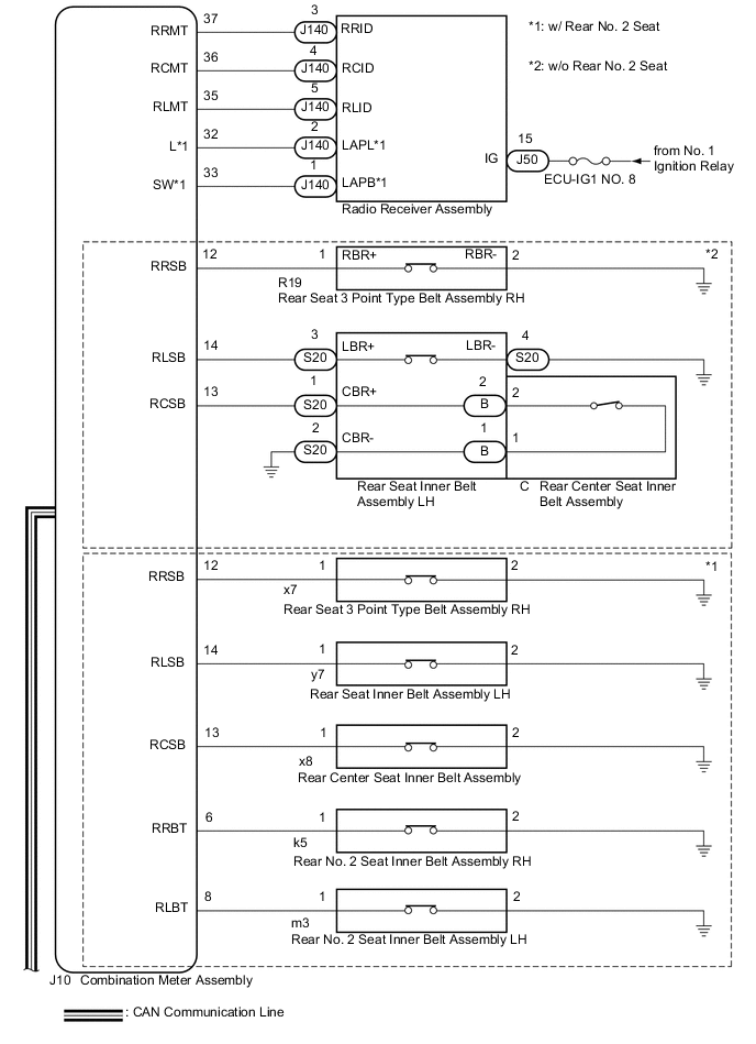
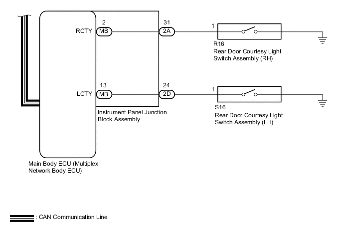
WIRING DIAGRAM
CAUTION / NOTICE / HINT
Note
-
The seat belt warning system (w/o Occupant Classification System) uses the CAN communication system. First, confirm that there are no malfunctions in the CAN communication system. Refer to the How to Proceed with Troubleshooting procedure.
-
Inspect the fuses for circuits related to this system before performing the following procedure.
PROCEDURE
-
READ VALUE USING GTS
-
Connect the GTS to the DLC3.
-
Turn the engine switch on (IG).
-
Turn the GTS on.
-
Enter the following menus: Body Electrical / Main Body / Data List.
-
Read the Data List according to the display on the GTS.
Body Electrical > Main Body > Data ListTester Display Measurement Item Range Normal Condition Diagnostic Note RR Door Courtesy SW Rear door courtesy light switch RH ON or OFF ON: Rear door RH open
OFF: Rear door RH closed
- RL Door Courtesy SW Rear door courtesy light switch LH ON or OFF ON: Rear door LH open
OFF: Rear door LH closed
-
Body Electrical > Main Body > Data ListTester Display RR Door Courtesy SW RL Door Courtesy SW OK The GTS display changes correctly in response to the rear door condition. Result Proceed to OK NG
NG 
GO TO LIGHTING SYSTEM Click here
OK 
-
-
CHECK REAR SEAT BELT WARNING
-
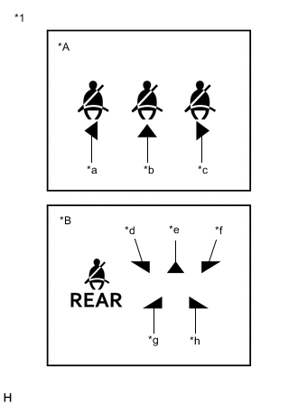
*A w/o Rear No. 2 Seat *B w/ Rear No. 2 Seat *1 Rear Seat Belt Warning Light (Radio Receiver Assembly) *a LH *b Center *c RH *d Rear No. 1 Seat LH *e Rear No. 1 Seat Center *f Rear No. 1 Seat RH *g Rear No. 2 Seat LH *h Rear No. 2 Seat RH Check the rear seat belt warning function.
Result Result Proceed to The rear seat belt warning lights (all seats) operate normally A The rear seat belt warning lights (all seats) do not operate normally B The rear seat belt warning light (RH) does not operate normally*1 C The rear seat belt warning light (center) does not operate normally*1 D The rear seat belt warning light (LH) does not operate normally*1 E The rear seat belt warning light (rear No. 1 seat RH) does not operate normally*2 F The rear seat belt warning light (rear No. 1 seat center) does not operate normally*2 G The rear seat belt warning light (rear No. 1 seat LH) does not operate normally*2 H The rear seat belt warning light (rear No. 2 seat RH) does not operate normally*2 I The rear seat belt warning light (rear No. 2 seat LH) does not operate normally*2 J
-
*1: w/o Rear No. 2 Seat
-
*2: w/ Rear No. 2 Seat
-
A
USE SIMULATION METHOD TO CHECK Click here
C 
READ VALUE USING GTS Click here
D
READ VALUE USING GTS Click here
E
READ VALUE USING GTS Click here
F
READ VALUE USING GTS Click here
G
READ VALUE USING GTS Click here
H
READ VALUE USING GTS Click here
I
READ VALUE USING GTS Click here
J
READ VALUE USING GTS Click here
B
-
-
CHECK HARNESS AND CONNECTOR (IG POWER SUPPLY - RADIO RECEIVER ASSEMBLY)
-
Disconnect the J50 radio receiver assembly connector.
-
Measure the voltage according to the value(s) in the table below.
Standard Voltage Tester Connection Condition Specified Condition J50-15 (IG) - Body ground Engine switch on (IG) 11 to 14 V J50-15 (IG) - Body ground Engine switch off Below 1 V Result Proceed to OK NG
NG
REPAIR OR REPLACE HARNESS OR CONNECTOR
OK
-
-
CHECK HARNESS AND CONNECTOR (RADIO RECEIVER ASSEMBLY - COMBINATION METER ASSEMBLY)
-
Reconnect the J50 radio receiver assembly connector.
-
Disconnect the J10 combination meter assembly connector.
-
Measure the voltage according to the value(s) in the table below.
Standard Voltage Tester Connection Condition Specified Condition J10-35 (RLMT) - Body ground Engine switch on (IG) 11 to 14 V J10-36 (RCMT) - Body ground Engine switch on (IG) 11 to 14 V J10-37 (RRMT) - Body ground Engine switch on (IG) 11 to 14 V J10-32 (L) - Body ground* Engine switch on (IG) 11 to 14 V J10-33 (SW) - Body ground* Engine switch on (IG) 11 to 14 V *: w/ Rear No. 2 Seat
Result Proceed to OK NG
NG
REPAIR OR REPLACE HARNESS OR CONNECTOR
OK
-
-
REPLACE RADIO RECEIVER ASSEMBLY
-
Temporarily replace the radio receiver assembly with a new or known good one.
for Radio and Display System: Click here
for Navigation System: Click here
Result Proceed to NEXT
NEXT
-
-
CHECK REAR SEAT BELT WARNING
-
*A w/o Rear No. 2 Seat *B w/ Rear No. 2 Seat *1 Rear Seat Belt Warning Light (Radio Receiver Assembly) *a LH *b Center *c RH *d Rear No. 1 Seat LH *e Rear No. 1 Seat Center *f Rear No. 1 Seat RH *g Rear No. 2 Seat LH *h Rear No. 2 Seat RH Check the rear seat belt warning function.
OK The rear seat belt warning lights (all seats) operate normally. Result Proceed to OK NG
OK
END (RADIO RECEIVER ASSEMBLY WAS DEFECTIVE)
NG
REPLACE COMBINATION METER ASSEMBLY Click here
-
-
READ VALUE USING GTS
-
Connect the GTS to the DLC3.
-
Turn the engine switch on (IG).
-
Turn the GTS on.
-
Enter the following menus: Body Electrical / Combination Meter / Data List.
-
Read the Data List according to the display on the GTS.
Body Electrical > Combination Meter > Data ListTester Display Measurement Item Range Normal Condition Diagnostic Note 2nd-Row Seatbelt Buckle (R) Rear RH seat belt buckle switch signal ON or OFF OFF: Rear RH seat belt fastened
ON: Rear RH seat belt not fastened
-
Body Electrical > Combination Meter > Data ListTester Display 2nd-Row Seatbelt Buckle (R) Result Result Proceed to ON or OFF does not appear on the GTS screen according to the rear seat belt condition A ON or OFF appears on the GTS screen according to the rear seat belt condition B
B
CHECK HARNESS AND CONNECTOR (COMBINATION METER ASSEMBLY - RADIO RECEIVER ASSEMBLY) Click here
A
-
-
CHECK HARNESS AND CONNECTOR (COMBINATION METER ASSEMBLY - REAR SEAT 3 POINT TYPE BELT ASSEMBLY RH - BODY GROUND)
-
Disconnect the J10 combination meter assembly connector.
-
Disconnect the R19 rear seat 3 point type belt assembly RH connector.
-
Measure the resistance according to the value(s) in the table below.
Standard Resistance Tester Connection Condition Specified Condition J10-12 (RRSB) - R19-1 (RBR+) Always Below 1 Ω J10-12 (RRSB) or R19-1 (RBR+) - Body ground Always 10 kΩ or higher R19-2 (RBR-) - Body ground Always Below 1 Ω Result Proceed to OK NG
OK
REPLACE REAR SEAT 3 POINT TYPE BELT ASSEMBLY RH Click here
NG
REPAIR OR REPLACE HARNESS OR CONNECTOR
-
-
CHECK HARNESS AND CONNECTOR (COMBINATION METER ASSEMBLY - RADIO RECEIVER ASSEMBLY)
-
Disconnect the J10 combination meter assembly connector.
-
Disconnect the J140 radio receiver assembly connector.
-
Measure the resistance according to the value(s) in the table below.
Standard Resistance Tester Connection Condition Specified Condition J10-37 (RRMT) - J140-3 (RRID) Always Below 1 Ω J10-37 (RRMT) or J140-3 (RRID) - Body ground Always 10 kΩ or higher Result Proceed to OK NG
NG
REPAIR OR REPLACE HARNESS OR CONNECTOR
OK
-
-
REPLACE RADIO RECEIVER ASSEMBLY
-
Temporarily replace the radio receiver assembly with a new or known good one.
for Radio and Display System: Click here
for Navigation System: Click here
Result Proceed to NEXT
NEXT
-
-
CHECK REAR SEAT BELT WARNING
-
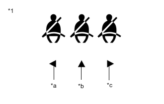
*1 Rear Seat Belt Warning Light (Radio Receiver Assembly) *a LH *b Center *c RH Check the rear seat belt warning function.
OK The rear seat belt warning light (RH) operates normally. Result Proceed to OK NG
OK
END (RADIO RECEIVER ASSEMBLY WAS DEFECTIVE)
NG
REPLACE COMBINATION METER ASSEMBLY Click here
-
-
READ VALUE USING GTS
-
Connect the GTS to the DLC3.
-
Turn the engine switch on (IG).
-
Turn the GTS on.
-
Enter the following menus: Body Electrical / Combination Meter / Data List.
-
Read the Data List according to the display on the GTS.
Body Electrical > Combination Meter > Data ListTester Display Measurement Item Range Normal Condition Diagnostic Note 2nd-Row Seatbelt Buckle (C) Rear center seat belt buckle switch signal ON or OFF OFF: Rear center seat belt fastened
ON: Rear center seat belt not fastened
-
Body Electrical > Combination Meter > Data ListTester Display 2nd-Row Seatbelt Buckle (C) Result Result Proceed to ON or OFF does not appear on the GTS screen according to the rear seat belt condition A ON or OFF appears on the GTS screen according to the rear seat belt condition B
B
CHECK HARNESS AND CONNECTOR (COMBINATION METER ASSEMBLY - RADIO RECEIVER ASSEMBLY) Click here
A
-
-
CHECK HARNESS AND CONNECTOR (COMBINATION METER ASSEMBLY - REAR SEAT INNER BELT ASSEMBLY LH - BODY GROUND)
-
Disconnect the J10 combination meter assembly connector.
-
Disconnect the S20 rear seat inner belt assembly LH connector.
-
Measure the resistance according to the value(s) in the table below.
Standard Resistance Tester Connection Condition Specified Condition J10-13 (RCSB) - S20-1 (CBR+) Always Below 1 Ω J10-13 (RCSB) or S20-1 (CBR+) - Body ground Always 10 kΩ or higher S20-2 (CBR-) - Body ground Always Below 1 Ω Result Proceed to OK NG
NG
REPAIR OR REPLACE HARNESS OR CONNECTOR
OK
-
-
INSPECT REAR SEAT INNER BELT ASSEMBLY LH
-
Remove the rear seat inner belt assembly LH.
-
Measure the resistance according to the value(s) in the table below.
Standard Resistance Tester Connection Condition Specified Condition S20-1 - B-2 Always Below 1 Ω S20-2 - B-1 Always Below 1 Ω Result Proceed to OK NG
OK
REPLACE REAR CENTER SEAT INNER BELT ASSEMBLY Click here
NG
REPLACE REAR SEAT INNER BELT ASSEMBLY LH Click here
-
-
CHECK HARNESS AND CONNECTOR (COMBINATION METER ASSEMBLY - RADIO RECEIVER ASSEMBLY)
-
Disconnect the J10 combination meter assembly connector.
-
Disconnect the J140 radio receiver assembly connector.
-
Measure the resistance according to the value(s) in the table below.
Standard Resistance Tester Connection Condition Specified Condition J10-36 (RCMT) - J140-4 (RCID) Always Below 1 Ω J10-36 (RCMT) or J140-4 (RCID) - Body ground Always 10 kΩ or higher Result Proceed to OK NG
NG
REPAIR OR REPLACE HARNESS OR CONNECTOR
OK
-
-
REPLACE RADIO RECEIVER ASSEMBLY
-
Temporarily replace the radio receiver assembly with a new or known good one.
for Radio and Display System: Click here
for Navigation System: Click here
Result Proceed to NEXT
NEXT
-
-
CHECK REAR SEAT BELT WARNING
-
*1 Rear Seat Belt Warning Light (Radio Receiver Assembly) *a LH *b Center *c RH Check the rear seat belt warning function.
OK The rear seat belt warning light (center) operates normally. Result Proceed to OK NG
OK
END (RADIO RECEIVER ASSEMBLY WAS DEFECTIVE)
NG
REPLACE COMBINATION METER ASSEMBLY Click here
-
-
READ VALUE USING GTS
-
Connect the GTS to the DLC3.
-
Turn the engine switch on (IG).
-
Turn the GTS on.
-
Enter the following menus: Body Electrical / Combination Meter / Data List.
-
Read the Data List according to the display on the GTS.
Body Electrical > Combination Meter > Data ListTester Display Measurement Item Range Normal Condition Diagnostic Note 2nd-Row Seatbelt Buckle (L) Rear LH seat belt buckle switch signal ON or OFF OFF: Rear LH seat belt fastened
ON: Rear LH seat belt not fastened
-
Body Electrical > Combination Meter > Data ListTester Display 2nd-Row Seatbelt Buckle (L) Result Result Proceed to ON or OFF does not appear on the GTS screen according to the rear seat belt condition A ON or OFF appears on the GTS screen according to the rear seat belt condition B
B
CHECK HARNESS AND CONNECTOR (COMBINATION METER ASSEMBLY - RADIO RECEIVER ASSEMBLY) Click here
A
-
-
CHECK HARNESS AND CONNECTOR (COMBINATION METER ASSEMBLY - REAR SEAT INNER BELT ASSEMBLY LH - BODY GROUND)
-
Disconnect the J10 combination meter assembly connector.
-
Disconnect the S20 rear seat inner belt assembly LH connector.
-
Measure the resistance according to the value(s) in the table below.
Standard Resistance Tester Connection Condition Specified Condition J10-14 (RLSB) - S20-3 (LBR+) Always Below 1 Ω J10-14 (RLSB) or S20-3 (LBR+) - Body ground Always 10 kΩ or higher S20-4 (LBR-) - Body ground Always Below 1 Ω Result Proceed to OK NG
OK
REPLACE REAR SEAT INNER BELT ASSEMBLY LH Click here
NG
REPAIR OR REPLACE HARNESS OR CONNECTOR
-
-
CHECK HARNESS AND CONNECTOR (COMBINATION METER ASSEMBLY - RADIO RECEIVER ASSEMBLY)
-
Disconnect the J10 combination meter assembly connector.
-
Disconnect the J140 radio receiver assembly connector.
-
Measure the resistance according to the value(s) in the table below.
Standard Resistance Tester Connection Condition Specified Condition J10-35 (RLMT) - J140-5 (RLID) Always Below 1 Ω J10-35 (RLMT) or J140-5 (RLID) - Body ground Always 10 kΩ or higher Result Proceed to OK NG
NG
REPAIR OR REPLACE HARNESS OR CONNECTOR
OK
-
-
REPLACE RADIO RECEIVER ASSEMBLY
-
Temporarily replace the radio receiver assembly with a new or known good one.
for Radio and Display System: Click here
for Navigation System: Click here
Result Proceed to NEXT
NEXT
-
-
CHECK REAR SEAT BELT WARNING
-
*1 Rear Seat Belt Warning Light (Radio Receiver Assembly) *a LH *b Center *c RH Check the rear seat belt warning function.
OK The rear seat belt warning light (LH) operates normally. Result Proceed to OK NG
OK
END (RADIO RECEIVER ASSEMBLY WAS DEFECTIVE)
NG
REPLACE COMBINATION METER ASSEMBLY Click here
-
-
READ VALUE USING GTS
-
Connect the GTS to the DLC3.
-
Turn the engine switch on (IG).
-
Turn the GTS on.
-
Enter the following menus: Body Electrical / Combination Meter / Data List.
-
Read the Data List according to the display on the GTS.
Body Electrical > Combination Meter > Data ListTester Display Measurement Item Range Normal Condition Diagnostic Note 2nd-Row Seatbelt Buckle (R) Rear No. 1 RH seat belt buckle switch signal ON or OFF OFF: Rear No. 1 RH seat belt fastened
ON: Rear No. 1 RH seat belt not fastened
-
Body Electrical > Combination Meter > Data ListTester Display 2nd-Row Seatbelt Buckle (R) Result Result Proceed to ON or OFF does not appear on the GTS screen according to the rear No. 1 seat belt condition A ON or OFF appears on the GTS screen according to the rear No. 1 seat belt condition B
B
CHECK HARNESS AND CONNECTOR (COMBINATION METER ASSEMBLY - RADIO RECEIVER ASSEMBLY) Click here
A
-
-
CHECK HARNESS AND CONNECTOR (COMBINATION METER ASSEMBLY - REAR SEAT 3 POINT TYPE BELT ASSEMBLY RH - BODY GROUND)
-
Disconnect the J10 combination meter assembly connector.
-
Disconnect the x7 rear seat 3 point type belt assembly RH connector.
-
Measure the resistance according to the value(s) in the table below.
Standard Resistance Tester Connection Condition Specified Condition J10-12 (RRSB) - x7-1 Always Below 1 Ω J10-12 (RRSB) or x7-1 - Body ground Always 10 kΩ or higher x7-2 - Body ground Always Below 1 Ω Result Proceed to OK NG
OK
REPLACE REAR SEAT 3 POINT TYPE BELT ASSEMBLY RH Click here
NG
REPAIR OR REPLACE HARNESS OR CONNECTOR
-
-
CHECK HARNESS AND CONNECTOR (COMBINATION METER ASSEMBLY - RADIO RECEIVER ASSEMBLY)
-
Disconnect the J10 combination meter assembly connector.
-
Disconnect the J140 radio receiver assembly connector.
-
Measure the resistance according to the value(s) in the table below.
Standard Resistance Tester Connection Condition Specified Condition J10-37 (RRMT) - J140-3 (RRID) Always Below 1 Ω J10-37 (RRMT) or J140-3 (RRID) - Body ground Always 10 kΩ or higher Result Proceed to OK NG
NG
REPAIR OR REPLACE HARNESS OR CONNECTOR
OK
-
-
REPLACE RADIO RECEIVER ASSEMBLY
-
Temporarily replace the radio receiver assembly with a new or known good one.
for Radio and Display System: Click here
for Navigation System: Click here
Result Proceed to NEXT
NEXT
-
-
CHECK REAR SEAT BELT WARNING
-
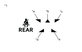
*1 Rear Seat Belt Warning Light (Radio Receiver Assembly) *a Rear No. 1 Seat LH *b Rear No. 1 Seat Center *c Rear No. 1 Seat RH *d Rear No. 2 Seat LH *e Rear No. 2 Seat RH Check the rear seat belt warning function.
OK The rear seat belt warning light (rear No. 1 seat RH) operates normally. Result Proceed to OK NG
OK
END (RADIO RECEIVER ASSEMBLY WAS DEFECTIVE)
NG
REPLACE COMBINATION METER ASSEMBLY Click here
-
-
READ VALUE USING GTS
-
Connect the GTS to the DLC3.
-
Turn the engine switch on (IG).
-
Turn the GTS on.
-
Enter the following menus: Body Electrical / Combination Meter / Data List.
-
Read the Data List according to the display on the GTS.
Body Electrical > Combination Meter > Data ListTester Display Measurement Item Range Normal Condition Diagnostic Note 2nd-Row Seatbelt Buckle (C) Rear No. 1 center seat belt buckle switch signal ON or OFF OFF: Rear No. 1 center seat belt fastened
ON: Rear No. 1 center seat belt not fastened
-
Body Electrical > Combination Meter > Data ListTester Display 2nd-Row Seatbelt Buckle (C) Result Result Proceed to ON or OFF does not appear on the GTS screen according to the rear No. 1 seat belt condition A ON or OFF appears on the GTS screen according to the rear No. 1 seat belt condition B
B
CHECK HARNESS AND CONNECTOR (COMBINATION METER ASSEMBLY - RADIO RECEIVER ASSEMBLY) Click here
A
-
-
CHECK HARNESS AND CONNECTOR (COMBINATION METER ASSEMBLY - REAR CENTER SEAT INNER BELT ASSEMBLY - BODY GROUND)
-
Disconnect the J10 combination meter assembly connector.
-
Disconnect the x8 rear center seat inner belt assembly connector.
-
Measure the resistance according to the value(s) in the table below.
Standard Resistance Tester Connection Condition Specified Condition J10-13 (RCSB) - x8-1 Always Below 1 Ω J10-13 (RCSB) or x8-1 - Body ground Always 10 kΩ or higher x8-2 - Body ground Always Below 1 Ω Result Proceed to OK NG
OK
REPLACE REAR CENTER SEAT INNER BELT ASSEMBLY Click here
NG
REPAIR OR REPLACE HARNESS OR CONNECTOR
-
-
CHECK HARNESS AND CONNECTOR (COMBINATION METER ASSEMBLY - RADIO RECEIVER ASSEMBLY)
-
Disconnect the J10 combination meter assembly connector.
-
Disconnect the J140 radio receiver assembly connector.
-
Measure the resistance according to the value(s) in the table below.
Standard Resistance Tester Connection Condition Specified Condition J10-36 (RCMT) - J140-4 (RCID) Always Below 1 Ω J10-36 (RCMT) or J140-4 (RCID) - Body ground Always 10 kΩ or higher Result Proceed to OK NG
NG
REPAIR OR REPLACE HARNESS OR CONNECTOR
OK
-
-
REPLACE RADIO RECEIVER ASSEMBLY
-
Temporarily replace the radio receiver assembly with a new or known good one.
for Radio and Display System: Click here
for Navigation System: Click here
Result Proceed to NEXT
NEXT
-
-
CHECK REAR SEAT BELT WARNING
-
*1 Rear Seat Belt Warning Light (Radio Receiver Assembly) *a Rear No. 1 Seat LH *b Rear No. 1 Seat Center *c Rear No. 1 Seat RH *d Rear No. 2 Seat LH *e Rear No. 2 Seat RH Check the rear seat belt warning function.
OK The rear seat belt warning light (rear No. 1 seat center) operates normally. Result Proceed to OK NG
OK
END (RADIO RECEIVER ASSEMBLY WAS DEFECTIVE)
NG
REPLACE COMBINATION METER ASSEMBLY Click here
-
-
READ VALUE USING GTS
-
Connect the GTS to the DLC3.
-
Turn the engine switch on (IG).
-
Turn the GTS on.
-
Enter the following menus: Body Electrical / Combination Meter / Data List.
-
Read the Data List according to the display on the GTS.
Body Electrical > Combination Meter > Data ListTester Display Measurement Item Range Normal Condition Diagnostic Note 2nd-Row Seatbelt Buckle (L) Rear No. 1 LH seat belt buckle switch signal ON or OFF OFF: Rear No. 1 LH seat belt fastened
ON: Rear No. 1 LH seat belt not fastened
-
Body Electrical > Combination Meter > Data ListTester Display 2nd-Row Seatbelt Buckle (L) Result Result Proceed to ON or OFF does not appear on the GTS screen according to the rear No. 1 seat belt condition A ON or OFF appears on the GTS screen according to the rear No. 1 seat belt condition B
B
CHECK HARNESS AND CONNECTOR (COMBINATION METER ASSEMBLY - RADIO RECEIVER ASSEMBLY) Click here
A
-
-
CHECK HARNESS AND CONNECTOR (COMBINATION METER ASSEMBLY - REAR SEAT INNER BELT ASSEMBLY LH - BODY GROUND)
-
Disconnect the J10 combination meter assembly connector.
-
Disconnect the y7 rear seat inner belt assembly LH connector.
-
Measure the resistance according to the value(s) in the table below.
Standard Resistance Tester Connection Condition Specified Condition J10-14 (RLSB) - y7-1 Always Below 1 Ω J10-14 (RLSB) or y7-1 - Body ground Always 10 kΩ or higher y7-2 - Body ground Always Below 1 Ω Result Proceed to OK NG
OK
REPLACE REAR SEAT INNER BELT ASSEMBLY LH Click here
NG
REPAIR OR REPLACE HARNESS OR CONNECTOR
-
-
CHECK HARNESS AND CONNECTOR (COMBINATION METER ASSEMBLY - RADIO RECEIVER ASSEMBLY)
-
Disconnect the J10 combination meter assembly connector.
-
Disconnect the J140 radio receiver assembly connector.
-
Measure the resistance according to the value(s) in the table below.
Standard Resistance Tester Connection Condition Specified Condition J10-35 (RLMT) - J140-5 (RLID) Always Below 1 Ω J10-35 (RLMT) or J140-5 (RLID) - Body ground Always 10 kΩ or higher Result Proceed to OK NG
NG
REPAIR OR REPLACE HARNESS OR CONNECTOR
OK
-
-
REPLACE RADIO RECEIVER ASSEMBLY
-
Temporarily replace the radio receiver assembly with a new or known good one.
for Radio and Display System: Click here
for Navigation System: Click here
Result Proceed to NEXT
NEXT
-
-
CHECK REAR SEAT BELT WARNING
-
*1 Rear Seat Belt Warning Light (Radio Receiver Assembly) *a Rear No. 1 Seat LH *b Rear No. 1 Seat Center *c Rear No. 1 Seat RH *d Rear No. 2 Seat LH *e Rear No. 2 Seat RH Check the rear seat belt warning function.
OK The rear seat belt warning light (rear No. 1 seat LH) operates normally. Result Proceed to OK NG
OK
END (RADIO RECEIVER ASSEMBLY WAS DEFECTIVE)
NG
REPLACE COMBINATION METER ASSEMBLY Click here
-
-
READ VALUE USING GTS
-
Connect the GTS to the DLC3.
-
Turn the engine switch on (IG).
-
Turn the GTS on.
-
Enter the following menus: Body Electrical / Combination Meter / Data List.
-
Read the Data List according to the display on the GTS.
Body Electrical > Combination Meter > Data ListTester Display Measurement Item Range Normal Condition Diagnostic Note 3rd-Row Seatbelt Buckle (R) Rear No. 2 RH seat belt buckle switch signal ON or OFF OFF: Rear No. 2 RH seat belt fastened
ON: Rear No. 2 RH seat belt not fastened
-
Body Electrical > Combination Meter > Data ListTester Display 3rd-Row Seatbelt Buckle (R) Result Result Proceed to ON or OFF does not appear on the GTS screen according to the rear No. 2 seat belt condition A ON or OFF appears on the GTS screen according to the rear No. 2 seat belt condition B
B
CHECK HARNESS AND CONNECTOR (COMBINATION METER ASSEMBLY - RADIO RECEIVER ASSEMBLY) Click here
A
-
-
CHECK HARNESS AND CONNECTOR (COMBINATION METER ASSEMBLY - REAR NO. 2 SEAT INNER BELT ASSEMBLY RH - BODY GROUND)
-
Disconnect the J10 combination meter assembly connector.
-
Disconnect the k5 rear No. 2 seat inner belt assembly RH connector.
-
Measure the resistance according to the value(s) in the table below.
Standard Resistance Tester Connection Condition Specified Condition J10-6 (RRBT) - k5-1 Always Below 1 Ω J10-6 (RRBT) or k5-1 - Body ground Always 10 kΩ or higher k5-2 - Body ground Always Below 1 Ω Result Proceed to OK NG
OK
REPLACE REAR NO. 2 SEAT INNER BELT ASSEMBLY RH Click here
NG
REPAIR OR REPLACE HARNESS OR CONNECTOR
-
-
CHECK HARNESS AND CONNECTOR (COMBINATION METER ASSEMBLY - RADIO RECEIVER ASSEMBLY)
-
Disconnect the J10 combination meter assembly connector.
-
Disconnect the J140 radio receiver assembly connector.
-
Measure the resistance according to the value(s) in the table below.
Standard Resistance Tester Connection Condition Specified Condition J10-33 (SW) - J140-1 (LAPB) Always Below 1 Ω J10-33 (SW) or J140-1 (LAPB) - Body ground Always 10 kΩ or higher Result Proceed to OK NG
NG
REPAIR OR REPLACE HARNESS OR CONNECTOR
OK
-
-
REPLACE RADIO RECEIVER ASSEMBLY
-
Temporarily replace the radio receiver assembly with a new or known good one.
for Radio and Display System: Click here
for Navigation System: Click here
Result Proceed to NEXT
NEXT
-
-
CHECK REAR SEAT BELT WARNING
-
*1 Rear Seat Belt Warning Light (Radio Receiver Assembly) *a Rear No. 1 Seat LH *b Rear No. 1 Seat Center *c Rear No. 1 Seat RH *d Rear No. 2 Seat LH *e Rear No. 2 Seat RH Check the rear seat belt warning function.
OK The rear seat belt warning light (rear No. 2 seat RH) operates normally. Result Proceed to OK NG
OK
END (RADIO RECEIVER ASSEMBLY WAS DEFECTIVE)
NG
REPLACE COMBINATION METER ASSEMBLY Click here
-
-
READ VALUE USING GTS
-
Connect the GTS to the DLC3.
-
Turn the engine switch on (IG).
-
Turn the GTS on.
-
Enter the following menus: Body Electrical / Combination Meter / Data List.
-
Read the Data List according to the display on the GTS.
Body Electrical > Combination Meter > Data ListTester Display Measurement Item Range Normal Condition Diagnostic Note 3rd-Row Seatbelt Buckle (L) Rear No. 2 LH seat belt buckle switch signal ON or OFF OFF: Rear No. 2 LH seat belt fastened
ON: Rear No. 2 LH seat belt not fastened
-
Body Electrical > Combination Meter > Data ListTester Display 3rd-Row Seatbelt Buckle (L) Result Result Proceed to ON or OFF does not appear on the GTS screen according to the rear No. 2 seat belt condition A ON or OFF appears on the GTS screen according to the rear No. 2 seat belt condition B
B
CHECK HARNESS AND CONNECTOR (COMBINATION METER ASSEMBLY - RADIO RECEIVER ASSEMBLY) Click here
A
-
-
CHECK HARNESS AND CONNECTOR (COMBINATION METER ASSEMBLY - REAR NO. 2 SEAT INNER BELT ASSEMBLY LH - BODY GROUND)
-
Disconnect the J10 combination meter assembly connector.
-
Disconnect the m3 rear No. 2 seat inner belt assembly LH connector.
-
Measure the resistance according to the value(s) in the table below.
Standard Resistance Tester Connection Condition Specified Condition J10-8 (RLBT) - m3-1 Always Below 1 Ω J10-8 (RLBT) or m3-1 - Body ground Always 10 kΩ or higher m3-2 - Body ground Always Below 1 Ω Result Proceed to OK NG
OK
REPLACE REAR NO. 2 SEAT INNER BELT ASSEMBLY LH Click here
NG
REPAIR OR REPLACE HARNESS OR CONNECTOR
-
-
CHECK HARNESS AND CONNECTOR (COMBINATION METER ASSEMBLY - RADIO RECEIVER ASSEMBLY)
-
Disconnect the J10 combination meter assembly connector.
-
Disconnect the J140 radio receiver assembly connector.
-
Measure the resistance according to the value(s) in the table below.
Standard Resistance Tester Connection Condition Specified Condition J10-32 (L) - J140-2 (LAPL) Always Below 1 Ω J10-32 (L) or J140-2 (LAPL) - Body ground Always 10 kΩ or higher Result Proceed to OK NG
NG
REPAIR OR REPLACE HARNESS OR CONNECTOR
OK
-
-
REPLACE RADIO RECEIVER ASSEMBLY
-
Temporarily replace the radio receiver assembly with a new or known good one.
for Radio and Display System: Click here
for Navigation System: Click here
Result Proceed to NEXT
NEXT
-
-
CHECK REAR SEAT BELT WARNING
-
*1 Rear Seat Belt Warning Light (Radio Receiver Assembly) *a Rear No. 1 Seat LH *b Rear No. 1 Seat Center *c Rear No. 1 Seat RH *d Rear No. 2 Seat LH *e Rear No. 2 Seat RH Check the rear seat belt warning function.
OK The rear seat belt warning light (rear No. 2 seat LH) operates normally. Result Proceed to OK NG
OK
END (RADIO RECEIVER ASSEMBLY WAS DEFECTIVE)
NG
REPLACE COMBINATION METER ASSEMBLY Click here
-