AIRBAG SYSTEM, Diagnostic DTC:B1660/43

| DTC Code | DTC Name |
|---|---|
| B1660/43 | Passenger Airbag ON/OFF Indicator Circuit Malfunction |
DESCRIPTION
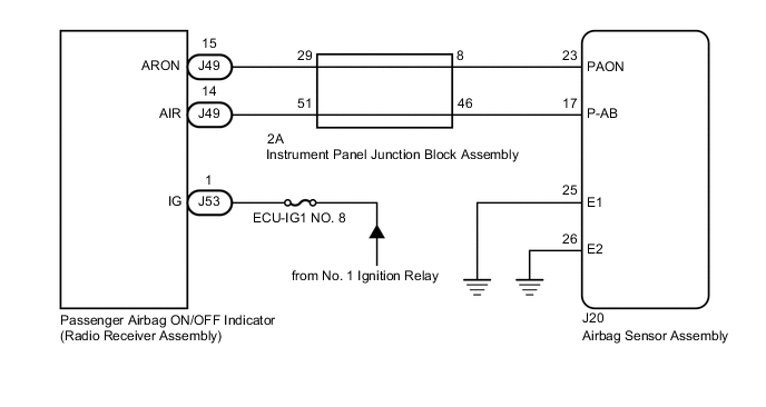
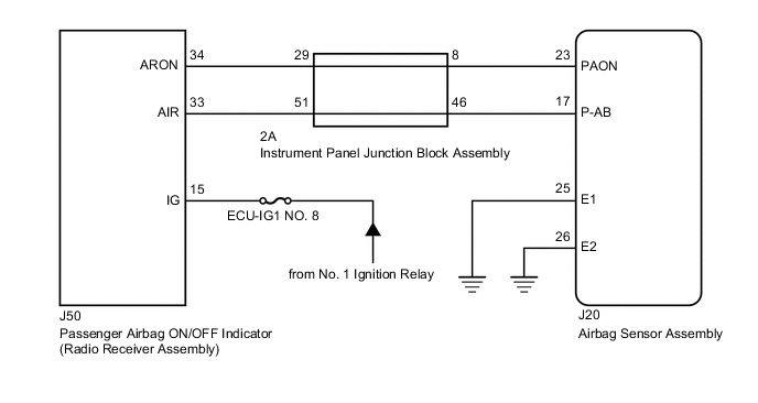
The passenger airbag ON/OFF indicator circuit consists of the airbag sensor assembly and passenger airbag ON/OFF indicator (radio receiver assembly).
The passenger airbag ON/OFF indicator indicates the operation condition of the instrument panel passenger airbag assembly and front seat cushion airbag assembly (passenger side).
DTC B1660/43 is stored when a malfunction is detected in the passenger airbag ON/OFF indicator circuit.
| DTC No. | Detection Item | DTC Detection Condition | Trouble Area | Test Mode / Check Mode |
|---|---|---|---|---|
| B1660/43 | Passenger Airbag ON/OFF Indicator Circuit Malfunction |
|
|
Does not apply to test/check mode |
WIRING DIAGRAM
-
w/o Navigation System:
-
w/ Navigation System:
CAUTION / NOTICE / HINT
Note
-
After turning the engine switch off, waiting time may be required before disconnecting the cable from the negative (-) battery terminal. Therefore, make sure to read the disconnecting the cable from the negative (-) battery terminal notices before proceeding with work.
-
Inspect the fuses for circuits related to this system before performing the following procedure.
PROCEDURE
-
CHECK PASSENGER AIRBAG ON/OFF INDICATOR CONDITION
-
Turn the engine switch on (IG).
-
Check the passenger airbag ON/OFF indicator operation.
Result Result Proceed to ON/OFF indicator illumination is always on. A ON/OFF indicator illumination is always off. B
B 
CHECK CONNECTORS Click here
A 
-
-
CHECK CONNECTORS
-
Turn the engine switch off.
-
Disconnect the cable from the negative (-) battery terminal.
CAUTION:
Wait at least 90 seconds after disconnecting the cable from the negative (-) battery terminal to disable the SRS system.
-
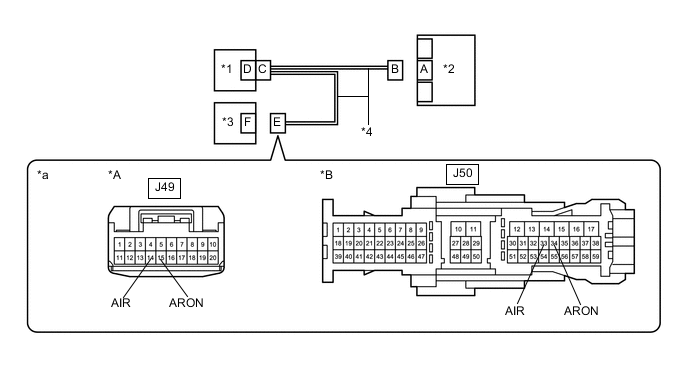
Check that the connectors are properly connected to the airbag sensor assembly, radio receiver assembly and instrument panel junction block assembly.
OK The connectors are properly connected. Tech Tips
If the connectors are not properly connected, reconnect the connectors and proceed to the next inspection.
-
Disconnect the connectors from the airbag sensor assembly, radio receiver assembly and instrument panel junction block assembly.
-
Check that the terminals of the connectors are not deformed or damaged.
OK The terminals are not deformed or damaged. Result Proceed to OK NG
NG 
REPLACE INSTRUMENT PANEL WIRE
OK
-
-
CHECK PASSENGER AIRBAG ON/OFF INDICATOR CONDITION
-
Connect the connector to the radio receiver assembly and instrument panel junction block assembly.
-
Connect the cable to the negative (-) battery terminal.
-
Turn the engine switch on (IG).
-
Check the passenger airbag ON/OFF indicator operation.
OK The passenger airbag ON/OFF indicator does not come on. Result Proceed to OK NG
NG
CHECK WIRE HARNESS (OPEN) Click here
OK
-
-
CHECK DTC
-
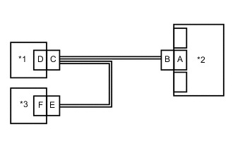
*1 Instrument Panel Junction Block Assembly *2 Airbag Sensor Assembly *3 Radio Receiver Assembly Turn the engine switch off.
-
Disconnect the cable from the negative (-) battery terminal.
CAUTION:
Wait at least 90 seconds after disconnecting the cable from the negative (-) battery terminal to disable the SRS system.
-
Connect the connector to the airbag sensor assembly.
-
Connect the cable to the negative (-) battery terminal.
-
Clear the DTCs stored in memory.
Body Electrical > SRS Airbag > Clear DTCs -
Turn the engine switch off.
-
Turn the engine switch on (IG), and wait for at least 60 seconds.
-
Check for DTCs.
Body Electrical > SRS Airbag > Trouble CodesOK DTC B1660/43 is not output. Tech Tips
Codes other than DTC B1660/43 may be output at this time, but they are not related to this check.
Result Proceed to OK NG
OK
USE SIMULATION METHOD TO CHECK Click here
NG
REPLACE AIRBAG SENSOR ASSEMBLY Click here
-
-
CHECK WIRE HARNESS (OPEN)
-
Turn the engine switch off.
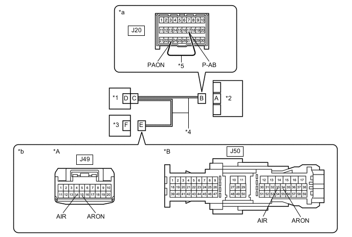
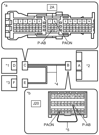
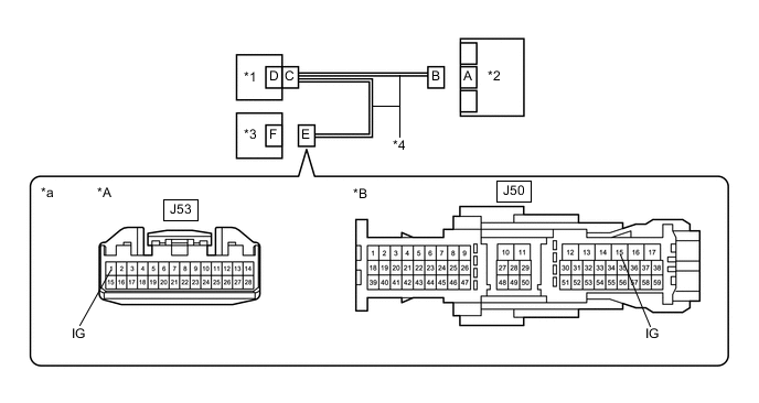
*A w/o Navigation System *B w/ Navigation System *1 Instrument Panel Junction Block Assembly *2 Airbag Sensor Assembly *3 Radio Receiver Assembly *4 Instrument Panel Wire *5 Service Wire - - *a Front view of wire harness connector
(to Airbag Sensor Assembly)
*b Front view of wire harness connector
(to Radio Receiver Assembly)
-
Disconnect the cable from the negative (-) battery terminal.
CAUTION:
Wait at least 90 seconds after disconnecting the cable from the negative (-) battery terminal to disable the SRS system.
-
Disconnect the connector from the radio receiver assembly.
-
Using a service wire, connect terminals 23 (PAON) and 17 (P-AB) of connector B.
Note
Do not forcibly insert the service wire into the terminals of the connector when connecting the wire.
-
Measure the resistance according to the value(s) in the table below.
Standard Resistance w/o Navigation System: Tester Connection Condition Specified Condition J49-15 (ARON) - J49-14 (AIR) Always Below 1 Ω w/ Navigation System: Tester Connection Condition Specified Condition J50-34 (ARON) - J50-33 (AIR) Always Below 1 Ω Result Proceed to OK NG
NG
CHECK INSTRUMENT PANEL WIRE (OPEN) Click here
OK
-
-
CHECK WIRE HARNESS (SHORT)
-
Disconnect the service wire from connector B.
*A w/o Navigation System *B w/ Navigation System *1 Instrument Panel Junction Block Assembly *2 Airbag Sensor Assembly *3 Radio Receiver Assembly *4 Instrument Panel Wire *a Front view of wire harness connector
(to Radio Receiver Assembly)
- - -
Measure the resistance according to the value(s) in the table below.
Standard Resistance w/o Navigation System: Tester Connection Condition Specified Condition J49-15 (ARON) - J49-14 (AIR) Always 1 MΩ or higher w/ Navigation System: Tester Connection Condition Specified Condition J50-34 (ARON) - J50-33 (AIR) Always 1 MΩ or higher Result Proceed to OK NG
NG
CHECK INSTRUMENT PANEL WIRE (SHORT) Click here
OK
-
-
CHECK WIRE HARNESS (SHORT TO B+)
-
Connect the cable to the negative (-) battery terminal.
*A w/o Navigation System *B w/ Navigation System *1 Instrument Panel Junction Block Assembly *2 Airbag Sensor Assembly *3 Radio Receiver Assembly *4 Instrument Panel Wire *a Front view of wire harness connector
(to Radio Receiver Assembly)
- - -
Turn the engine switch on (IG).
-
Measure the voltage according to the value(s) in the table below.
Standard Voltage w/o Navigation System: Tester Connection Condition Specified Condition J49-15 (ARON) - Body ground Engine switch on (IG) Below 1 V J49-14 (AIR) - Body ground Engine switch on (IG) Below 1 V w/ Navigation System: Tester Connection Condition Specified Condition J50-34 (ARON) - Body ground Engine switch on (IG) Below 1 V J50-33 (AIR) - Body ground Engine switch on (IG) Below 1 V -
Turn the engine switch off.
-
Disconnect the cable from the negative (-) battery terminal.
CAUTION:
Wait at least 90 seconds after disconnecting the cable from the negative (-) battery terminal to disable the SRS system.
Result Proceed to OK NG
NG
CHECK INSTRUMENT PANEL WIRE (SHORT TO B+) Click here
OK
-
-
CHECK WIRE HARNESS (SHORT TO GROUND)
-
Measure the resistance according to the value(s) in the table below.
*A w/o Navigation System *B w/ Navigation System *1 Instrument Panel Junction Block Assembly *2 Airbag Sensor Assembly *3 Radio Receiver Assembly *4 Instrument Panel Wire *a Front view of wire harness connector
(to Radio Receiver Assembly)
- - Standard Resistance w/o Navigation System: Tester Connection Condition Specified Condition J49-15 (ARON) - Body ground Always 1 MΩ or higher J49-14 (AIR) - Body ground Always 1 MΩ or higher w/ Navigation System: Tester Connection Condition Specified Condition J50-34 (ARON) - Body ground Always 1 MΩ or higher J50-33 (AIR) - Body ground Always 1 MΩ or higher Result Proceed to OK NG
OK
REPLACE RADIO RECEIVER ASSEMBLY w/o Navigation System: Click here
REPLACE RADIO RECEIVER ASSEMBLY w/ Navigation System: Click hereNG
-
-
CHECK INSTRUMENT PANEL WIRE (SHORT TO GROUND)
-
*1 Instrument Panel Junction Block Assembly *2 Airbag Sensor Assembly *3 Radio Receiver Assembly *4 Instrument Panel Wire *a Front view of wire harness connector
(to Instrument Panel Junction Block Assembly)
Disconnect the connector from the instrument panel junction block assembly.
-
Measure the resistance according to the value(s) in the table below.
Standard Resistance Tester Connection Condition Specified Condition 2A-8 (PAON) - Body ground Always 1 MΩ or higher 2A-29 (PAON) - Body ground Always 1 MΩ or higher 2A-46 (P-AB) - Body ground Always 1 MΩ or higher 2A-51 (P-AB) - Body ground Always 1 MΩ or higher Result Proceed to OK NG
OK
REPLACE INSTRUMENT PANEL JUNCTION BLOCK ASSEMBLY
NG
REPLACE INSTRUMENT PANEL WIRE
-
-
CHECK INSTRUMENT PANEL WIRE (SHORT TO B+)
-
*1 Instrument Panel Junction Block Assembly *2 Airbag Sensor Assembly *3 Radio Receiver Assembly *4 Instrument Panel Wire *a Front view of wire harness connector
(to Instrument Panel Junction Block Assembly)
Disconnect the connector from the instrument panel junction block assembly.
-
Measure the resistance according to the value(s) in the table below.
Standard Resistance Tester Connection Condition Specified Condition 2A-8 (PAON) - Other terminals Always 1 MΩ or higher 2A-29 (PAON) - Other terminals Always 1 MΩ or higher 2A-46 (P-AB) - Other terminals Always 1 MΩ or higher 2A-51 (P-AB) - Other terminals Always 1 MΩ or higher Result Proceed to OK NG
OK
REPLACE INSTRUMENT PANEL JUNCTION BLOCK ASSEMBLY
NG
REPLACE INSTRUMENT PANEL WIRE
-
-
CHECK INSTRUMENT PANEL WIRE (SHORT)
-
*1 Instrument Panel Junction Block Assembly *2 Airbag Sensor Assembly *3 Radio Receiver Assembly *4 Instrument Panel Wire *a Front view of wire harness connector
(to Instrument Panel Junction Block Assembly)
Disconnect the connector from the instrument panel junction block assembly.
-
Measure the resistance according to the value(s) in the table below.
Standard Resistance Tester Connection Condition Specified Condition 2A-8 (PAON) - 2A-46 (P-AB) Always 1 MΩ or higher 2A-29 (PAON) - 2A-51 (P-AB) Always 1 MΩ or higher Result Proceed to OK NG
OK
REPLACE INSTRUMENT PANEL JUNCTION BLOCK ASSEMBLY
NG
REPLACE INSTRUMENT PANEL WIRE
-
-
CHECK INSTRUMENT PANEL WIRE (OPEN)
-
*1 Instrument Panel Junction Block Assembly *2 Airbag Sensor Assembly *3 Radio Receiver Assembly *4 Instrument Panel Wire *5 Service Wire *a Front view of wire harness connector
(to Instrument Panel Junction Block Assembly)
*b Front view of wire harness connector
(to Airbag Sensor Assembly)
Disconnect the connector from the instrument panel junction block assembly.
Tech Tips
The service wire has already been inserted into connector B.
-
Measure the resistance according to the value(s) in the table below.
Standard Resistance Tester Connection Condition Specified Condition 2A-8 (PAON) - 2A-46 (P-AB) Always Below 1 Ω -
Disconnect the service wire from connector B.
-
Using a service wire, connect terminals 15*1 or 34*2 (ARON) and 14*1 or 33*2 (AIR) of connector E.
Note
Do not forcibly insert the service wire into the terminals of the connector when connecting the wire.
-
*1: w/o Navigation System
-
*2: w/ Navigation System
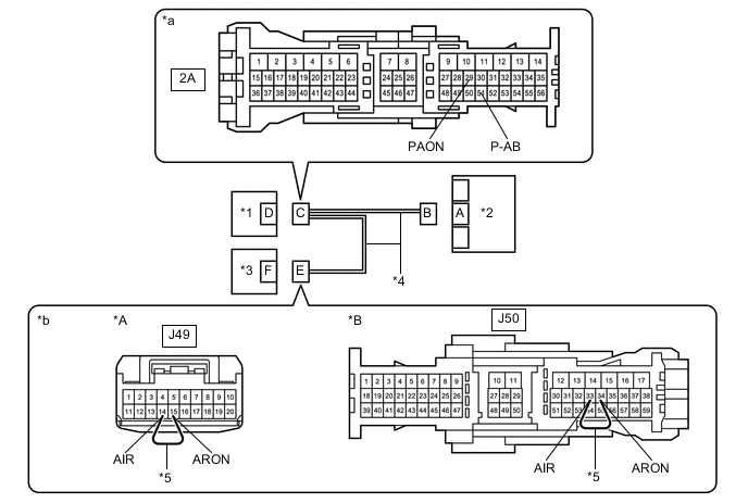
*A w/o Navigation System *B w/ Navigation System *1 Instrument Panel Junction Block Assembly *2 Airbag Sensor Assembly *3 Radio Receiver Assembly *4 Instrument Panel Wire *5 Service Wire - - *a Front view of wire harness connector
(to Instrument Panel Junction Block Assembly)
*b Front view of wire harness connector
(to Radio Receiver Assembly)
-
-
Measure the resistance according to the value(s) in the table below.
Standard Resistance Tester Connection Condition Specified Condition 2A-29 (PAON) - 2A-51 (P-AB) Always Below 1 Ω -
Disconnect the service wire from connector E.
Result Proceed to OK NG
OK
REPLACE INSTRUMENT PANEL JUNCTION BLOCK ASSEMBLY
NG
REPLACE INSTRUMENT PANEL WIRE
-
-
CHECK CONNECTORS
-
Turn the engine switch off.
-
Disconnect the cable from the negative (-) battery terminal.
CAUTION:
Wait at least 90 seconds after disconnecting the cable from the negative (-) battery terminal to disable the SRS system.
-
Check that the connectors are properly connected to the airbag sensor assembly, radio receiver assembly and instrument panel junction block assembly.
OK The connectors are properly connected. Tech Tips
If the connectors are not properly connected, reconnect the connectors and proceed to the next inspection.
-
Disconnect the connectors from the airbag sensor assembly, radio receiver assembly and instrument panel junction block assembly.
-
Check that the terminals of the connectors are not deformed or damaged.
OK The terminals are not deformed or damaged. Result Proceed to OK NG
NG
REPLACE INSTRUMENT PANEL WIRE
OK
-
-
CHECK WIRE HARNESS (OPEN)
-
Connect the connector to the instrument panel junction block assembly.
*A w/o Navigation System *B w/ Navigation System *1 Instrument Panel Junction Block Assembly *2 Airbag Sensor Assembly *3 Radio Receiver Assembly *4 Instrument Panel Wire *5 Service Wire - - *a Front view of wire harness connector
(to Airbag Sensor Assembly)
*b Front view of wire harness connector
(to Radio Receiver Assembly)
-
Using a service wire, connect terminals 23 (PAON) and 17 (P-AB) of connector B.
Note
Do not forcibly insert the service wire into the terminals of the connector when connecting the wire.
-
Measure the resistance according to the value(s) in the table below.
Standard Resistance w/o Navigation System: Tester Connection Condition Specified Condition J49-15 (ARON) - J49-14 (AIR) Always Below 1 Ω w/ Navigation System: Tester Connection Condition Specified Condition J50-34 (ARON) - J50-33 (AIR) Always Below 1 Ω Result Proceed to OK NG
NG
CHECK INSTRUMENT PANEL WIRE (OPEN) Click here
OK
-
-
CHECK WIRE HARNESS (SHORT)
-
Disconnect the service wire from connector B.
*A w/o Navigation System *B w/ Navigation System *1 Instrument Panel Junction Block Assembly *2 Airbag Sensor Assembly *3 Radio Receiver Assembly *4 Instrument Panel Wire *a Front view of wire harness connector
(to Radio Receiver Assembly)
- - -
Measure the resistance according to the value(s) in the table below.
Standard Resistance w/o Navigation System: Tester Connection Condition Specified Condition J49-15 (ARON) - J49-14 (AIR) Always 1 MΩ or higher w/ Navigation System: Tester Connection Condition Specified Condition J50-34 (ARON) - J50-33 (AIR) Always 1 MΩ or higher Result Proceed to OK NG
NG
CHECK INSTRUMENT PANEL WIRE (SHORT) Click here
OK
-
-
CHECK WIRE HARNESS (SHORT TO B+)
-
Connect the cable to the negative (-) battery terminal.
*A w/o Navigation System *B w/ Navigation System *1 Instrument Panel Junction Block Assembly *2 Airbag Sensor Assembly *3 Radio Receiver Assembly *4 Instrument Panel Wire *a Front view of wire harness connector
(to Radio Receiver Assembly)
- - -
Turn the engine switch on (IG).
-
Measure the voltage according to the value(s) in the table below.
Standard Voltage w/o Navigation System: Tester Connection Condition Specified Condition J49-15 (ARON) - Body ground Engine switch on (IG) Below 1 V J49-14 (AIR) - Body ground Engine switch on (IG) Below 1 V w/ Navigation System: Tester Connection Condition Specified Condition J50-34 (ARON) - Body ground Engine switch on (IG) Below 1 V J50-33 (AIR) - Body ground Engine switch on (IG) Below 1 V -
Turn the engine switch off.
-
Disconnect the cable from the negative (-) battery terminal.
CAUTION:
Wait at least 90 seconds after disconnecting the cable from the negative (-) battery terminal to disable the SRS system.
Result Proceed to OK NG
NG
CHECK INSTRUMENT PANEL WIRE (SHORT TO B+) Click here
OK
-
-
CHECK WIRE HARNESS (SHORT TO GROUND)
-
Measure the resistance according to the value(s) in the table below.
*A w/o Navigation System *B w/ Navigation System *1 Instrument Panel Junction Block Assembly *2 Airbag Sensor Assembly *3 Radio Receiver Assembly *4 Instrument Panel Wire *a Front view of wire harness connector
(to Radio Receiver Assembly)
- - Standard Resistance w/o Navigation System: Tester Connection Condition Specified Condition J49-15 (ARON) - Body ground Always 1 MΩ or higher J49-14 (AIR) - Body ground Always 1 MΩ or higher w/ Navigation System: Tester Connection Condition Specified Condition J50-34 (ARON) - Body ground Always 1 MΩ or higher J50-33 (AIR) - Body ground Always 1 MΩ or higher Result Proceed to OK NG
NG
CHECK INSTRUMENT PANEL WIRE (SHORT TO GROUND) Click here
OK
-
-
CHECK PASSENGER AIRBAG ON/OFF INDICATOR (SOURCE VOLTAGE)
-
Connect the cable to the negative (-) battery terminal.
*A w/o Navigation System *B w/ Navigation System *1 Instrument Panel Junction Block Assembly *2 Airbag Sensor Assembly *3 Radio Receiver Assembly *4 Instrument Panel Wire *a Front view of wire harness connector
(to Radio Receiver Assembly)
- - -
Turn the engine switch on (IG).
-
Measure the voltage according to the value(s) in the table below.
Standard Voltage w/o Navigation System: Tester Connection Condition Specified Condition J53-1 (IG) - Body ground Engine switch on (IG) 11 to 14 V w/ Navigation System: Tester Connection Condition Specified Condition J50-15 (IG) - Body ground Engine switch on (IG) 11 to 14 V -
Turn the engine switch off.
-
Disconnect the cable from the negative (-) battery terminal.
CAUTION:
Wait at least 90 seconds after disconnecting the cable from the negative (-) battery terminal to disable the SRS system.
Result Proceed to OK NG
NG
REPLACE WIRE HARNESS OR BATTERY
OK
-
-
CHECK PASSENGER AIRBAG ON/OFF INDICATOR
-
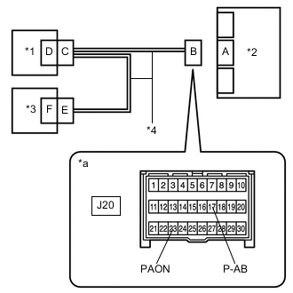
*1 Instrument Panel Junction Block Assembly *2 Airbag Sensor Assembly *3 Radio Receiver Assembly *4 Instrument Panel Wire *a Front view of wire harness connector
(to Airbag Sensor Assembly)
Connect the connector to the radio receiver assembly.
-
Connect the cable to the negative (-) battery terminal.
-
Turn the engine switch on (IG).
-
Check the passenger airbag ON/OFF indicator according to the conditions in the table below.
OK Terminal Connection Condition Specified Condition J20-23 (PAON) - Body ground Engine switch on (IG) "ON" comes on J20-17 (P-AB) - Body ground Engine switch on (IG) "OFF" comes on -
Turn the engine switch off.
-
Disconnect the cable from the negative (-) battery terminal.
CAUTION:
Wait at least 90 seconds after disconnecting the cable from the negative (-) battery terminal to disable the SRS system.
Result Proceed to OK NG
NG
REPLACE RADIO RECEIVER ASSEMBLY w/o Navigation System: Click here
REPLACE RADIO RECEIVER ASSEMBLY w/ Navigation System: Click hereOK
-
-
CHECK DTC
-
*1 Instrument Panel Junction Block Assembly *2 Airbag Sensor Assembly *3 Radio Receiver Assembly Connect the connector to the airbag sensor assembly.
-
Connect the cable to the negative (-) battery terminal.
-
Clear the DTCs stored in memory.
Body Electrical > SRS Airbag > Clear DTCs -
Turn the engine switch off.
-
Turn the engine switch on (IG), and wait for at least 60 seconds.
-
Check for DTCs.
Body Electrical > SRS Airbag > Trouble CodesOK DTC B1660/43 is not output. Tech Tips
Codes other than DTC B1660/43 may be output at this time, but they are not related to this check.
Result Proceed to OK NG
OK
USE SIMULATION METHOD TO CHECK Click here
NG
REPLACE AIRBAG SENSOR ASSEMBLY Click here
-
-
CHECK INSTRUMENT PANEL WIRE (SHORT TO GROUND)
-
*1 Instrument Panel Junction Block Assembly *2 Airbag Sensor Assembly *3 Radio Receiver Assembly *4 Instrument Panel Wire *a Front view of wire harness connector
(to Instrument Panel Junction Block Assembly)
Disconnect the connector from the instrument panel junction block assembly.
-
Measure the resistance according to the value(s) in the table below.
Standard Resistance Tester Connection Condition Specified Condition 2A-8 (PAON) - Body ground Always 1 MΩ or higher 2A-29 (PAON) - Body ground Always 1 MΩ or higher 2A-46 (P-AB) - Body ground Always 1 MΩ or higher 2A-51 (P-AB) - Body ground Always 1 MΩ or higher Result Proceed to OK NG
OK
REPLACE INSTRUMENT PANEL JUNCTION BLOCK ASSEMBLY
NG
REPLACE INSTRUMENT PANEL WIRE
-
-
CHECK INSTRUMENT PANEL WIRE (SHORT TO B+)
-
*1 Instrument Panel Junction Block Assembly *2 Airbag Sensor Assembly *3 Radio Receiver Assembly *4 Instrument Panel Wire *a Front view of wire harness connector
(to Instrument Panel Junction Block Assembly)
Disconnect the connector from the instrument panel junction block assembly.
-
Measure the resistance according to the value(s) in the table below.
Standard Resistance Tester Connection Condition Specified Condition 2A-8 (PAON) - Other terminals Always 1 MΩ or higher 2A-29 (PAON) - Other terminals Always 1 MΩ or higher 2A-46 (P-AB) - Other terminals Always 1 MΩ or higher 2A-51 (P-AB) - Other terminals Always 1 MΩ or higher Result Proceed to OK NG
OK
REPLACE INSTRUMENT PANEL JUNCTION BLOCK ASSEMBLY
NG
REPLACE INSTRUMENT PANEL WIRE
-
-
CHECK INSTRUMENT PANEL WIRE (SHORT)
-
*1 Instrument Panel Junction Block Assembly *2 Airbag Sensor Assembly *3 Radio Receiver Assembly *4 Instrument Panel Wire *a Front view of wire harness connector
(to Instrument Panel Junction Block Assembly)
Disconnect the connector from the instrument panel junction block assembly.
-
Measure the resistance according to the value(s) in the table below.
Standard Resistance Tester Connection Condition Specified Condition 2A-8 (PAON) - 2A-46 (P-AB) Always 1 MΩ or higher 2A-29 (PAON) - 2A-51 (P-AB) Always 1 MΩ or higher Result Proceed to OK NG
OK
REPLACE INSTRUMENT PANEL JUNCTION BLOCK ASSEMBLY
NG
REPLACE INSTRUMENT PANEL WIRE
-
-
CHECK INSTRUMENT PANEL WIRE (OPEN)
-
*1 Instrument Panel Junction Block Assembly *2 Airbag Sensor Assembly *3 Radio Receiver Assembly *4 Instrument Panel Wire *5 Service Wire *a Front view of wire harness connector
(to Instrument Panel Junction Block Assembly)
*b Front view of wire harness connector
(to Airbag Sensor Assembly)
Disconnect the connector from the instrument panel junction block assembly.
Tech Tips
The service wire has already been inserted into connector B.
-
Measure the resistance according to the value(s) in the table below.
Standard Resistance Tester Connection Condition Specified Condition 2A-8 (PAON) - 2A-46 (P-AB) Always Below 1 Ω -
Disconnect the service wire from connector B.
-
Using a service wire, connect terminals 15*1 or 34*2 (ARON) and 14*1 or 33*2 (AIR) of connector E.
Note
Do not forcibly insert the service wire into the terminals of the connector when connecting the wire.
-
*1: w/o Navigation System
-
*2: w/ Navigation System
*A w/o Navigation System *B w/ Navigation System *1 Instrument Panel Junction Block Assembly *2 Airbag Sensor Assembly *3 Radio Receiver Assembly *4 Instrument Panel Wire *5 Service Wire - - *a Front view of wire harness connector
(to Instrument Panel Junction Block Assembly)
*b Front view of wire harness connector
(to Radio Receiver Assembly)
-
-
Measure the resistance according to the value(s) in the table below.
Standard Resistance Tester Connection Condition Specified Condition 2A-29 (PAON) - 2A-51 (P-AB) Always Below 1 Ω -
Disconnect the service wire from connector E.
Result Proceed to OK NG
OK
REPLACE INSTRUMENT PANEL JUNCTION BLOCK ASSEMBLY
NG
REPLACE INSTRUMENT PANEL WIRE
-