METER / GAUGE SYSTEM, Diagnostic DTC:B150A
| DTC Code | DTC Name |
|---|---|
| B150A | Lost Communication with HMI-LAN |
DESCRIPTION
The combination meter assembly receives text data signals from the radio receiver assembly via local bus communication.
Based on these signals, audio and visual system or navigation system information is displayed on the multi-information display.
This DTC is stored when the combination meter assembly cannot receive the signal.
| DTC No. | Detection Item | DTC Detection Condition | Trouble Area | Memory | Note |
|---|---|---|---|---|---|
| B150A | Lost Communication with HMI-LAN | After the combination meter assembly receives a registration information signal, which is sent by the radio receiver assembly when the engine switch is on (ACC), 1 or more times, the combination meter assembly cannot receive the signal for 30 seconds or more. |
|
DTC stored | - |
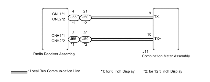
WIRING DIAGRAM
-
w/ Navigation System
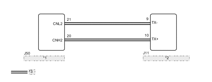
*1 Radio Receiver Assembly *2 Combination Meter Assembly *3 Local Bus Communication Line -
w/ Audio and Visual System
CAUTION / NOTICE / HINT
Tech Tips
DTC B150A may be stored if the battery voltage dropped.
PROCEDURE
-
CONFIRM MODEL
-
Choose the model to be inspected.
Result Result Proceed to w/ Navigation System A w/ Audio and Visual System B
B 
CHECK FOR DTC Click here
A 
-
-
CHECK FOR DTC
-
Check if navigation system DTCs are output.
Body Electrical > Navigation System > Trouble CodesResult Result Proceed to Navigation system DTCs are not output. A Navigation system DTCs are output. B
B 
GO TO NAVIGATION SYSTEM Click here
A
-
-
CHECK HARNESS AND CONNECTOR (COMBINATION METER ASSEMBLY - RADIO RECEIVER ASSEMBLY)
-
Disconnect the J11 combination meter assembly connector.
-
Disconnect the J50 radio receiver assembly connector.
-
Measure the resistance according to the value(s) in the table below.
Standard Resistance Tester Connection Condition Specified Condition J11-9 (TX-) - J50-21 (CNL2) Always Below 1 Ω J11-10 (TX+) - J50-20 (CNH2) Always Below 1 Ω J11-9 (TX-) or J50-21 (CNL2) - Body ground Always 10 kΩ or higher J11-10 (TX+) or J50-20 (CNH2) - Body ground Always 10 kΩ or higher Result Proceed to OK NG
NG
REPAIR OR REPLACE HARNESS OR CONNECTOR
OK
-
-
REPLACE COMBINATION METER ASSEMBLY
-
Replace the combination meter assembly with a new or known good one.
-
Turn the engine switch on (IG) and wait 30 seconds.
Note
A maximum of 30 seconds is required to send/receive the registration information between the combination meter assembly and radio receiver assembly.
-
Operate the steering pad switch assembly and check that the audio tab illuminates.
-
Check for DTCs.
Body Electrical > Combination Meter > Trouble CodesResult Result Proceed to The audio tab illuminates and DTC B150A is not output. A The audio tab does not illuminate and DTC B150A is output. B
A
END
B
REPLACE RADIO RECEIVER ASSEMBLY Click here
-
-
CHECK FOR DTC
-
Check if audio and visual system DTCs are output.
for 8 Inch Display: Click here
for 12.3 Inch Display: Click here
Body Electrical > Navigation System > Trouble CodesResult Result Proceed to Audio and visual system DTCs are not output. A Audio and visual system DTCs are output. B
B
GO TO AUDIO AND VISUAL SYSTEM for 8 Inch Display: Click here
GO TO AUDIO AND VISUAL SYSTEM for 12.3 Inch Display: Click hereA
-
-
CHECK HARNESS AND CONNECTOR (COMBINATION METER ASSEMBLY - RADIO RECEIVER ASSEMBLY)
-
Disconnect the J11 combination meter assembly connector.
-
Disconnect the J55*1 or J50*2 radio receiver assembly connector.
-
Measure the resistance according to the value(s) in the table below.
Standard Resistance Tester Connection Condition Specified Condition J11-9 (TX-) - J55-4 (CNL1)*1 Always Below 1 Ω J11-10 (TX+) - J55-3 (CNH1)*1 Always Below 1 Ω J11-9 (TX-) or J55-4 (CNL1) - Body ground*1 Always 10 kΩ or higher J11-10 (TX+) or J55-3 (CNH1) - Body ground*1 Always 10 kΩ or higher J11-9 (TX-) - J50-21 (CNL2)*2 Always Below 1 Ω J11-10 (TX+) - J50-20 (CNH2)*2 Always Below 1 Ω J11-9 (TX-) or J50-21 (CNL2) - Body ground*2 Always 10 kΩ or higher J11-10 (TX+) or J50-20 (CNH2) - Body ground*2 Always 10 kΩ or higher
-
*1: for 8 Inch Display
-
*2: for 12.3 Inch Display
Result Proceed to OK NG -
NG
REPAIR OR REPLACE HARNESS OR CONNECTOR
OK
-
-
REPLACE COMBINATION METER ASSEMBLY
-
Replace the combination meter assembly with a new or known good one.
-
Turn the engine switch on (IG) and wait 30 seconds.
Note
A maximum of 30 seconds is required to send/receive the registration information between the combination meter assembly and radio receiver assembly.
-
Operate the steering pad switch assembly and check that the audio tab illuminates.
-
Check for DTCs.
Body Electrical > Combination Meter > Trouble CodesResult Result Proceed to The audio tab illuminates and DTC B150A is not output. A The audio tab does not illuminate and DTC B150A is output. B
A
END
B
REPLACE RADIO RECEIVER ASSEMBLY for 8 Inch Display: Click here
REPLACE RADIO RECEIVER ASSEMBLY for 12.3 Inch Display: Click here -