CAN COMMUNICATION SYSTEM TERMINALS OF ECU
Note
-
After turning the engine switch off, waiting time may be required before disconnecting the cable from the negative (-) battery terminal. Therefore, make sure to read the disconnecting the cable from the negative (-) battery terminal notices before proceeding with work.
-
Turn the engine switch off before measuring the resistances between CAN main bus lines and between CAN branch lines.
-
Turn the engine switch off before inspecting CAN bus lines for a short to ground.
-
Before measuring the resistance of the CAN bus, turn the engine switch off and leave the vehicle for 1 minute or more without operating the key or any switches, or opening or closing the doors. After that, disconnect the cable from the negative (-) battery terminal and leave the vehicle for 1 minute or more before measuring the resistance.
-
This section describes the standard values for all CAN related components.
Tech Tips
-
Operating the engine switch, any other switches or a door triggers related ECU and sensor communication on the CAN. This communication will cause the resistance value to change.
-
Even after DTCs are cleared, if a DTC is stored again after driving the vehicle for a while, the malfunction may be occurring due to vibration of the vehicle. In such a case, wiggling the ECUs or wire harness while performing the inspection below may help determine the cause of the malfunction.
-
NO. 1 CAN JUNCTION CONNECTOR
-
Check the No. 1 CAN junction connector.
-
Connection diagram
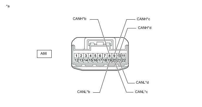
*a Front view of wire harness connector
(to No. 1 CAN Junction Connector)
*b to No. 8 CAN Junction Connector
(for Bus 4)
*c to Network Gateway ECU
(for Bus 4)
*d to Skid Control ECU (Brake Actuator Assembly)
(for Bus 4)
-
Check the connection diagram of the components which are connected to the No. 1 CAN junction connector.
Terminal No. (Symbol) Wiring Color Connected to A86-8 (CANH) SB No. 8 CAN junction connector
(for bus 4)
A86-19 (CANL) W A86-9 (CANH) GR Network gateway ECU
(for bus 4)
A86-20 (CANL) W A86-10 (CANH) B Skid control ECU (brake actuator assembly)
(for bus 4)
A86-21 (CANL) W
-
-
-
NO. 3 CAN JUNCTION CONNECTOR
-
Check the No. 3 CAN junction connector.
-
Connection diagram
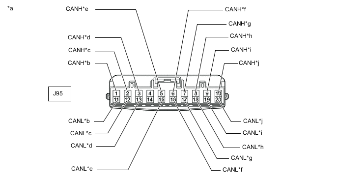
*a Front view of wire harness connector
(to No. 3 CAN Junction Connector)
*b to Network Gateway ECU
(for Bus 1)
*c to Parking Assist ECU
(w/ Panoramic View Monitor System)
(for Bus 1)
*d to Clearance Warning ECU Assembly
(w/ LEXUS Parking Assist-sensor System)
(for Bus 1)
*e to Millimeter Wave Radar Sensor Assembly
(w/ Lexus Safety System +)
(for Bus 1)
*f to Front Television Camera Assembly
(w/ Panoramic View Monitor System)
(for Bus 1)
*g to Driving Support ECU Assembly
(w/ Lexus Safety System +)
(for Bus 1)
*h to Forward Recognition Camera
(w/ Lexus Safety System +)
(for Bus 1)
*i to Side Camera RH (Outer Rear View Mirror Assembly RH)
(w/ Panoramic View Monitor System)
(for Bus 1)
*j to No. 10 CAN Junction Connector
(for Bus 1)
-
Check the connection diagram of the components which are connected to the No. 3 CAN junction connector.
Terminal No. (Symbol) Wiring Color Connected to J95-1 (CANH) GR Network gateway ECU
(for bus 1)
J95-11 (CANL) W J95-2 (CANH) LG Parking assist ECU*1
(for bus 1)
J95-12 (CANL) W J95-3 (CANH) L Clearance warning ECU assembly*2
(for bus 1)
J95-13 (CANL) W J95-5 (CANH) G Millimeter wave radar sensor assembly*3
(for bus 1)
J95-15 (CANL) W J95-6 (CANH) P Front television camera assembly*1
(for bus 1)
J95-16 (CANL) W J95-7 (CANH) R Driving support ECU assembly*3
(for bus 1)
J95-17 (CANL) W J95-8 (CANH) BE Forward recognition camera*3
(for bus 1)
J95-18 (CANL) W J95-9 (CANH) SB Side camera RH (outer rear view mirror assembly RH)*1
(for bus 1)
J95-19 (CANL) W J95-10 (CANH) Y No. 10 CAN junction connector
(for bus 1)
J95-20 (CANL) W
-
*1: w/ Panoramic View Monitor System
-
*2: w/ LEXUS Parking Assist-sensor System
-
*3: w/ Lexus Safety System +
-
-
-
-
NO. 5 CAN JUNCTION CONNECTOR
-
Check the No. 5 CAN junction connector.
-
Connection diagram
*a Front view of wire harness connector
(to No. 5 CAN Junction Connector)
*b to Network Gateway ECU
(for Bus 5)
*c to Combination Meter Mirror ECU (Headup Display)
(w/ Headup Display System)
(for Bus 5)
*d to Headlight ECU Sub-assembly LH
(for Bus 5)
*e to Main Body ECU (Multiplex Network Body ECU)
(for Bus 5)
*f to Air Conditioning Amplifier Assembly
(for Bus 5)
*g to Combination Meter Assembly
(for Bus 5)
*h to Certification ECU (Smart Key ECU Assembly)
(for Bus 5)
-
Check the connection diagram of the components which are connected to the No. 5 CAN junction connector.
Terminal No. (Symbol) Wiring Color Connected to J97-1 (CANH) B Network gateway ECU
(for bus 5)
J97-12 (CANL) W J97-2 (CANH) P Combination meter mirror ECU (headup display)*
(for bus 5)
J97-13 (CANL) W J97-3 (CANH) Y Headlight ECU sub-assembly LH
(for bus 5)
J97-14 (CANL) W J97-4 (CANH) L Main body ECU (multiplex network body ECU)
(for bus 5)
J97-15 (CANL) W J97-5 (CANH) LG Air conditioning amplifier assembly
(for bus 5)
J97-16 (CANL) W J97-6 (CANH) GR Combination meter assembly
(for bus 5)
J97-17 (CANL) W J97-7 (CANH) P Certification ECU (smart key ECU assembly)
(for bus 5)
J97-18 (CANL) W
-
*: w/ Headup Display System
-
-
-
-
NO. 6 CAN JUNCTION CONNECTOR
-
Check the No. 6 CAN junction connector.
-
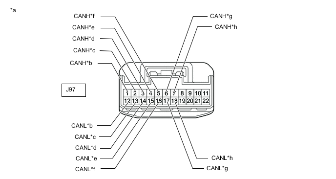
Connection diagram
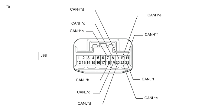
*a Front view of wire harness connector
(to No. 6 CAN Junction Connector)
*b to Network Gateway ECU
(for Bus 3)
*c to Option Connector (Bus Buffer ECU)
(w/ Option Connector (Bus Buffer ECU))
(for Bus 3)
*d to Telematics Transceiver
(w/ Manual (SOS) Switch)
(for Bus 3)
*e to Radio Receiver Assembly
(for Bus 3)
*f to Network Gateway ECU
(for Bus 3)
-
Check the connection diagram of the components which are connected to the No. 6 CAN junction connector.
Terminal No. (Symbol) Wiring Color Connected to J98-7 (CANH) Y Network gateway ECU
(for bus 3)
J98-18 (CANL) W J98-8 (CANH) SB Option connector (bus buffer ECU)*1
(for bus 3)
J98-19 (CANL) W J98-9 (CANH) L Telematics transceiver*2
(for bus 3)
J98-20 (CANL) W J98-10 (CANH) BE Radio receiver assembly
(for bus 3)
J98-21 (CANL) W J98-11 (CANH) SB Network gateway ECU
(for bus 3)
J98-22 (CANL) W
-
*1: w/ Option Connector (Bus Buffer ECU)
-
*2: w/ Manual (SOS) Switch
-
-
-
-
NO. 7 CAN JUNCTION CONNECTOR
-
Check the No. 7 CAN junction connector.
-
Connection diagram
*a Front view of wire harness connector
(to No. 7 CAN Junction Connector)
*b to Airbag Sensor Assembly
(for Bus 4)
*c to Steering Sensor
(for Bus 4)
*d to Yaw Rate Sensor Assembly
(w/ TFT Meter Type Combination Meter Assembly)
(for Bus 4)
*e to Power Steering ECU Assembly
(for Bus 4)
*f to No. 12 CAN Junction Connector
(for Bus 4)
*g to Engine Stop and Start ECU
(w/ Stop and Start System)
(for Bus 2)
*h to ECM
(w/ Stop and Start System)
(for Bus 2)
*i to Network Gateway ECU
(w/ Stop and Start System)
(for Bus 2)
- - -
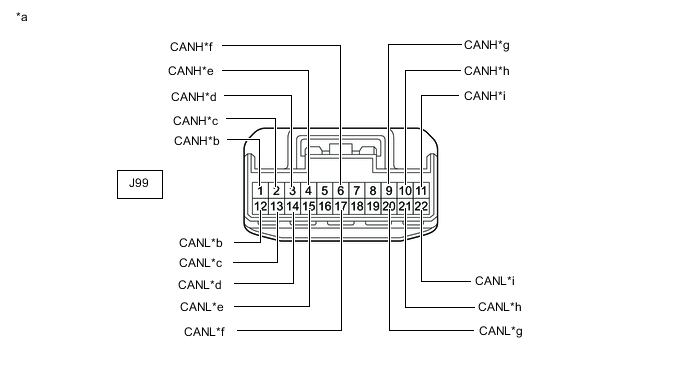
Check the connection diagram of the components which are connected to the No. 7 CAN junction connector.
Terminal No. (Symbol) Wiring Color Connected to J99-1 (CANH) B Airbag sensor assembly
(for bus 4)
J99-12 (CANL) W J99-2 (CANH) R Steering sensor
(for bus 4)
J99-13 (CANL) W J99-3 (CANH) P Yaw rate sensor assembly*1
(for bus 4)
J99-14 (CANL) W J99-4 (CANH) GR Power steering ECU assembly
(for bus 4)
J99-15 (CANL) W J99-6 (CANH) LG No. 12 CAN junction connector
(for bus 4)
J99-17 (CANL) W J99-9 (CANH) SB Engine stop and start ECU*2
(for bus 2)
J99-20 (CANL) W J99-10 (CANH) B ECM*2
(for bus 2)
J99-21 (CANL) W J99-11 (CANH) G Network gateway ECU*2
(for bus 2)
J99-22 (CANL) W
-
*1: w/ TFT Meter Type Combination Meter Assembly
-
*2: w/ Stop and Start System
-
-
-
-
NO. 8 CAN JUNCTION CONNECTOR
-
Check the No. 8 CAN junction connector.
-
Connection diagram
*a Front view of wire harness connector
(to No. 8 CAN Junction Connector)
*b to No. 9 CAN Junction Connector
(for Bus 4)
*c to No. 1 CAN Junction Connector
(for Bus 4)
*d to Occupant Detection ECU
(w/ 12.3 Inch Display Type Audio and Visual System)
(for Bus 4)
*e to 4WD ECU Assembly
(for AWD)
(for Bus 4)
*f to No. 11 CAN Junction Connector
(for Sub Bus 1)
*g to Position Control ECU and Switch Assembly RH
(w/ Seat Position Memory System)
(for Sub Bus 1)
*h to No. 1 CAN Junction Terminal
(for Sub Bus 1)
*i to Outer Mirror Control ECU Assembly (for Driver Side)
(for RHD)
(for Sub Bus 1)
*j to Outer Mirror Control ECU Assembly (for Front Passenger Side)
(for LHD)
(for Sub Bus 1)
-
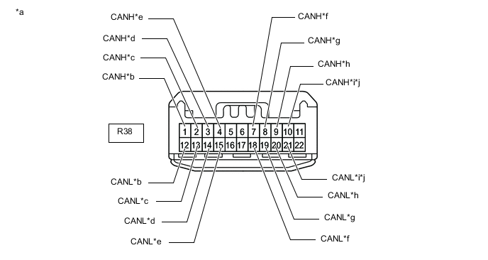
Check the connection diagram of the components which are connected to the No. 8 CAN junction connector.
Terminal No. (Symbol) Wiring Color Connected to R38-1 (CANH) B No. 9 CAN junction connector
(for bus 4)
R38-12 (CANL) W R38-2 (CANH) LG No. 1 CAN junction connector
(for bus 4)
R38-13 (CANL) W R38-3 (CANH) B Occupant detection ECU*1
(for bus 4)
R38-14 (CANL) W R38-4 (CANH) B 4WD ECU assembly*2
(for bus 4)
R38-15 (CANL) W R38-7 (CANH) W No. 11 CAN junction connector
(for sub bus 1)
R38-18 (CANL) B R38-8 (CANH) W Position control ECU and switch assembly RH*3
(for sub bus 1)
R38-19 (CANL) B R38-9 (CANH) W No. 1 CAN junction terminal
(for sub bus 1)
R38-20 (CANL) R R38-10 (CANH) P Outer mirror control ECU assembly (for driver side)*4
(for sub bus 1)
R38-21 (CANL) LG R38-10 (CANH) P Outer mirror control ECU assembly (for front passenger side)*5
(for sub bus 1)
R38-21 (CANL) LG
-
*1: w/ 12.3 Inch Display Type Audio and Visual System
-
*2: for AWD
-
*3: w/ Seat Position Memory System
-
*4: for RHD
-
*5: for LHD
-
-
-
-
NO. 9 CAN JUNCTION CONNECTOR
-
Check the No. 9 CAN junction connector.
-
Connection diagram
*a Front view of wire harness connector
(to No. 9 CAN Junction Connector)
*b to No. 12 CAN Junction Connector
(for Bus 4)
*c to Tire Pressure Warning ECU and Receiver
(for Tire Pressure Warning ECU and Receiver Integrated with Electrical Key Receiver / Tire Pressure Warning ECU and Receiver (Stand Alone) (Quarter Panel))
(for Bus 4)
*d to No. 8 CAN Junction Connector
(for Bus 4)
-
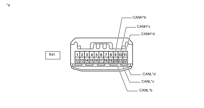
Check the connection diagram of the components which are connected to the No. 9 CAN junction connector.
Terminal No. (Symbol) Wiring Color Connected to R41-9 (CANH) L No. 12 CAN junction connector
(for bus 4)
R41-20 (CANL) W R41-10 (CANH) R Tire pressure warning ECU and receiver*
(for bus 4)
R41-21 (CANL) W R41-11 (CANH) B No. 8 CAN junction connector
(for bus 4)
R41-22 (CANL) W
-
*: for Tire Pressure Warning ECU and Receiver Integrated with Electrical Key Receiver / Tire Pressure Warning ECU and Receiver (Stand Alone) (Quarter Panel)
-
-
-
-
NO. 10 CAN JUNCTION CONNECTOR
-
Check the No. 10 CAN junction connector.
Tech Tips
Connectors that connect to the CAN junction connector can be distinguished by the color of their CAN bus lines. When the connectors have been disconnected from the CAN junction connector, reconnecting the connectors to non-original positions on the CAN junction connector does not affect system performance. However, it is preferred to reconnect the connectors to their original positions to avoid negative effects on the wiring such as tension on the wire harnesses, and to make future maintenance easier.
-
Connection diagram
*a Component with harness connected
(No. 10 CAN Junction Connector)
*b to Network Gateway ECU
(for Bus 1)
*c to No. 3 CAN Junction Connector
(for Bus 1)
*d to Blind Spot Monitor Sensor LH
(w/ Blind Spot Monitor System)
(for Bus 1)
*e to Rear Television Camera Assembly
(w/ Panoramic View Monitor System or Parking Assist Monitor System w/o Parallel Parking Assist Function)
(for Bus 1)
*f to Side Camera LH (Outer Rear View Mirror Assembly LH)
(w/ Panoramic View Monitor System)
(for Bus 1)
-
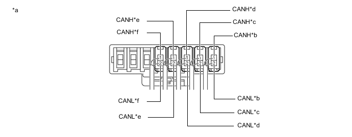
Check the connection diagram of the components which are connected to the No. 10 CAN junction connector.
Terminal No. (Symbol) Wiring Color Connected to S56-1 (CANH) G Network gateway ECU
(for bus 1)
S56-2 (CANL) W S57-1 (CANH) LG No. 3 CAN junction connector
(for bus 1)
S57-2 (CANL) W S58-1 (CANH) V Blind spot monitor sensor LH*1
(for bus 1)
S58-2 (CANL) W S59-1 (CANH) P Rear television camera assembly*2
(for bus 1)
S59-2 (CANL) W S60-1 (CANH) B Side camera LH (outer rear view mirror assembly LH)*3
(for bus 1)
S60-2 (CANL) W
-
*1: w/ Blind Spot Monitor System
-
*2: w/ Panoramic View Monitor System or Parking Assist Monitor System w/o Parallel Parking Assist Function
-
*3: w/ Panoramic View Monitor System
-
-
-
-
NO. 11 CAN JUNCTION CONNECTOR
-
Check the No. 11 CAN junction connector.
-
Connection diagram
*a Front view of wire harness connector
(to No. 11 CAN Junction Connector)
*b to No. 8 CAN Junction Connector
(for Sub Bus 1)
*c to Multiplex Tilt and Telescopic ECU
(for Sub Bus 1)
*d to Main Body ECU (Multiplex Network Body ECU)
(for Sub Bus 1)
*e to Position Control ECU and Switch Assembly LH
(w/ Seat Position Memory System)
(for Sub Bus 1)
*f to Multiplex Network Door ECU
(w/ Power Back Door System)
(for Sub Bus 1)
*g to Outer Mirror Control ECU Assembly (for Front Passenger Side)
(for RHD)
(for Sub Bus 1)
*h to Outer Mirror Control ECU Assembly (for Driver Side)
(for LHD)
(for Sub Bus 1)
-
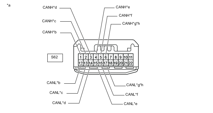
Check the connection diagram of the components which are connected to the No. 11 CAN junction connector.
Terminal No. (Symbol) Wiring Color Connected to S62-1 (CANH) W No. 8 CAN junction connector
(for sub bus 1)
S62-12 (CANL) B S62-2 (CANH) W Multiplex tilt and telescopic ECU
(for sub bus 1)
S62-13 (CANL) V S62-3 (CANH) W Main body ECU (multiplex network body ECU)
(for sub bus 1)
S62-14 (CANL) R S62-4 (CANH) W Position control ECU and switch assembly LH*1
(for sub bus 1)
S62-15 (CANL) B S62-5 (CANH) W Multiplex network door ECU*2
(for sub bus 1)
S62-16 (CANL) L S62-6 (CANH) W Outer mirror control ECU assembly (for front passenger side)*3
(for sub bus 1)
S62-17 (CANL) G S62-6 (CANH) W Outer mirror control ECU assembly (for driver side)*4
(for sub bus 1)
S62-17 (CANL) G
-
*1: w/ Seat Position Memory System
-
*2: w/ Power Back Door System
-
*3: for RHD
-
*4: for LHD
-
-
-
-
NO. 12 CAN JUNCTION CONNECTOR
-
Check the No. 12 CAN junction connector.
-
Connection diagram
*a Front view of wire harness connector
(to No. 12 CAN Junction Connector)
*b to No. 7 CAN Junction Connector
(for Bus 4)
*c to No. 9 CAN Junction Connector
(for Bus 4)
*d to Tire Pressure Warning ECU and Receiver
(for Tire Pressure Warning ECU and Receiver (Stand Alone) (Roof))
(for Bus 4)
*e to Absorber Control ECU
(w/ AVS)
(for Bus 4)
- - -
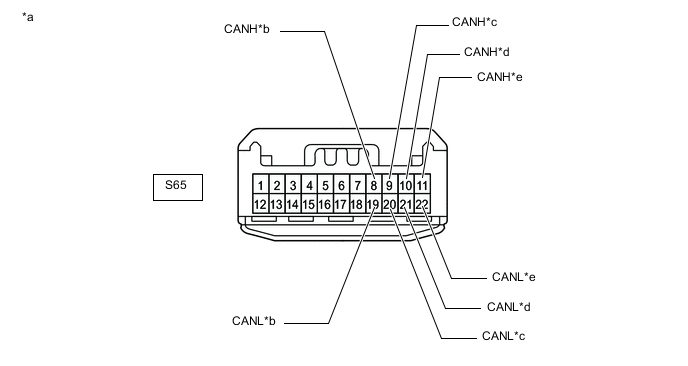
Check the connection diagram of the components which are connected to the No. 12 CAN junction connector.
Terminal No. (Symbol) Wiring Color Connected to S65-8 (CANH) L No. 7 CAN junction connector
(for bus 4)
S65-19 (CANL) W S65-9 (CANH) G No. 9 CAN junction connector
(for bus 4)
S65-20 (CANL) W S65-10 (CANH) B Tire pressure warning ECU and receiver*1
(for bus 4)
S65-21 (CANL) W S65-11 (CANH) R Absorber control ECU*2
(for bus 4)
S65-22 (CANL) W
-
*1: for Tire Pressure Warning ECU and Receiver (Stand Alone) (Roof)
-
*2: w/ AVS
-
-
-
-
NO. 1 CAN JUNCTION TERMINAL
-
Check the No. 1 CAN junction terminal.
-
Connection diagram

*a Front view of wire harness connector
(to No. 1 CAN Junction Terminal)
- - -
Check the connection diagram of the components which are connected to the No. 1 CAN junction terminal.
Terminal No. (Symbol) Wiring Color Connected to R39-3 (CANH) W No. 8 CAN junction connector
(for sub bus 1)
R39-2 (CANL) R
-
-
-
DLC3
-
Disconnect the cable from the negative (-) battery terminal.
-
Measure the resistance according to the value(s) in the table below.
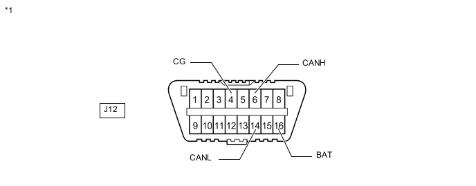
*1 DLC3 - -
-
-
NETWORK GATEWAY ECU
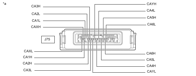
*a Component without harness connected
(Network Gateway ECU)
- -
-
Disconnect the cable from the negative (-) battery terminal.
-
Disconnect the J75 network gateway ECU connector.
-
Measure the resistance according to the value(s) in the table below.
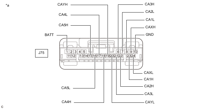
*a Front view of wire harness connector
(to Network Gateway ECU)
- -
-
-
STEERING SENSOR
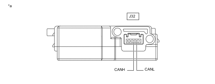
*a Component without harness connected
(Steering Sensor)
- -
-
Disconnect the cable from the negative (-) battery terminal.
-
Disconnect the J32 steering sensor connector.
-
Measure the resistance according to the value(s) in the table below.

*a Front view of wire harness connector
(to Steering Sensor)
- -
-
-
YAW RATE SENSOR ASSEMBLY (w/ TFT Meter Type Combination Meter Assembly)
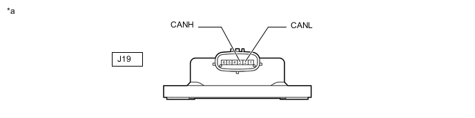
*a Component without harness connected
(Yaw Rate Sensor Assembly)
- -
-
Disconnect the cable from the negative (-) battery terminal.
-
Disconnect the J19 yaw rate sensor assembly connector.
-
Measure the resistance according to the value(s) in the table below.
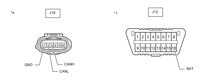
*1 DLC3 - - *a Front view of wire harness connector
(to Yaw Rate Sensor Assembly)
- -
-
-
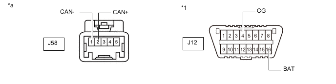
OPTION CONNECTOR (BUS BUFFER ECU) (w/ Option Connector (Bus Buffer ECU))
-
Disconnect the cable from the negative (-) battery terminal.
-
Disconnect the J58 option connector (bus buffer ECU).*
*: When a dealer-installed option is installed.
-
Measure the resistance according to the value(s) in the table below.
*1 DLC3 - - *a Front view of wire harness connector
(to Option Connector (Bus Buffer ECU))
- -
-
-
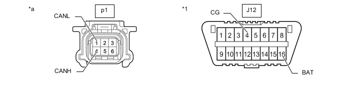
FRONT TELEVISION CAMERA ASSEMBLY (w/ Panoramic View Monitor System)

*a Component without harness connected
(Front Television Camera Assembly)
- -
-
Disconnect the cable from the negative (-) battery terminal.
-
Disconnect the p1 front television camera assembly connector.
*1 DLC3 - - *a Front view of wire harness connector
(to Front Television Camera Assembly)
- - -
Measure the resistance according to the value(s) in the table below.
-
-
SIDE CAMERA RH (OUTER REAR VIEW MIRROR ASSEMBLY RH) (w/ Panoramic View Monitor System)

*a Component without harness connected
(Side Camera RH (Outer Rear View Mirror Assembly RH))
- -
-
Disconnect the cable from the negative (-) battery terminal.
-
Disconnect the M1 side camera RH (outer rear view mirror assembly RH) connector.

*1 DLC3 - - *a Front view of wire harness connector
(to Side Camera RH (Outer Rear View Mirror Assembly RH))
- - -
Measure the resistance according to the value(s) in the table below.
-
-
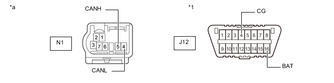
SIDE CAMERA LH (OUTER REAR VIEW MIRROR ASSEMBLY LH) (w/ Panoramic View Monitor System)

*a Component without harness connected
(Side Camera LH (Outer Rear View Mirror Assembly LH))
- -
-
Disconnect the cable from the negative (-) battery terminal.
-
Disconnect the N1 side camera LH (outer rear view mirror assembly LH) connector.
*1 DLC3 - - *a Front view of wire harness connector
(to Side Camera LH (Outer Rear View Mirror Assembly LH))
- - -
Measure the resistance according to the value(s) in the table below.
-
-
REAR TELEVISION CAMERA ASSEMBLY (w/ Panoramic View Monitor System or Parking Assist Monitor System w/o Parallel Parking Assist Function)
Refer to Terminals of ECU for Parking Assist Monitor System (w/o Parallel parking assist function) for further details.
-
Disconnect the cable from the negative (-) battery terminal.
-
Disconnect the Z11 rear television camera assembly connector.

*1 DLC3 - - *a Front view of wire harness connector
(to Rear Television Camera Assembly)
- - -
Measure the resistance according to the value(s) in the table below.
-
-
COMBINATION METER MIRROR ECU (HEADUP DISPLAY) (w/ Headup Display System)
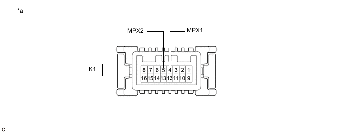
*a Component without harness connected
(Combination Meter Mirror ECU (Headup Display))
- -
-
Disconnect the cable from the negative (-) battery terminal.
-
Disconnect the K1 combination meter mirror ECU (headup display) connector.
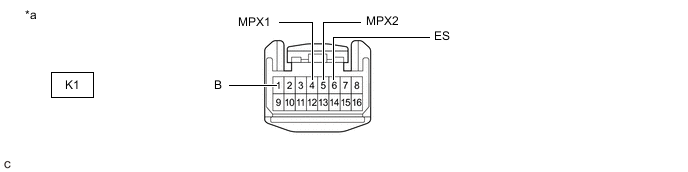
*a Front view of wire harness connector
(to Combination Meter Mirror ECU (Headup Display))
- - -
Measure the resistance according to the value(s) in the table below.
-
-
BLIND SPOT MONITOR SENSOR LH (w/ Blind Spot Monitor System)
Refer to Terminals of ECU for Blind Spot Monitor System for further details.
-
Disconnect the cable from the negative (-) battery terminal.
-
Disconnect the X2 blind spot monitor sensor LH connector.
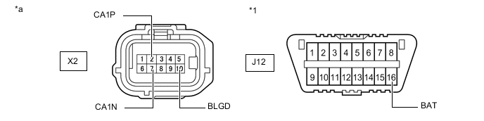
*1 DLC3 - - *a Front view of wire harness connector
(to Blind Spot Monitor Sensor LH)
- - -
Measure the resistance according to the value(s) in the table below.
-
-
DRIVING SUPPORT ECU ASSEMBLY (w/ Lexus Safety System +)
Refer to Terminals of ECU for Pre-crash Safety System for further details.
-
Disconnect the cable from the negative (-) battery terminal.
-
Disconnect the A72 driving support ECU assembly connector.
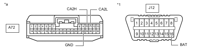
*1 DLC3 - - *a Front view of wire harness connector
(to Driving Support ECU Assembly)
- - -
Measure the resistance according to the value(s) in the table below.
-
-
MILLIMETER WAVE RADAR SENSOR ASSEMBLY (w/ Lexus Safety System +)
Refer to Terminals of ECU for Dynamic Radar Cruise Control System for further details.
-
Disconnect the cable from the negative (-) battery terminal.
-
Disconnect the A70 millimeter wave radar sensor assembly connector.
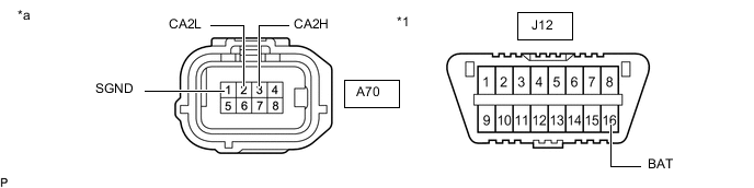
*1 DLC3 - - *a Front view of wire harness connector
(to Millimeter Wave Radar Sensor Assembly)
- - -
Measure the resistance according to the value(s) in the table below.
-
-
CLEARANCE WARNING ECU ASSEMBLY (w/ LEXUS Parking Assist-sensor System)
Refer to Terminals of ECU for Lexus Parking Assist-sensor System for further details.
Click here (w/o Intelligent Clearance Sonar System)
Click here (w/ Intelligent Clearance Sonar System)
-
Disconnect the cable from the negative (-) battery terminal.
-
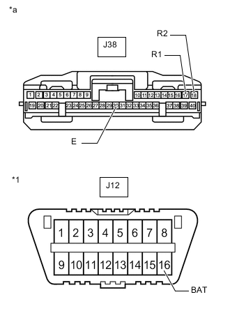
*1 DLC3 *a Front view of wire harness connector
(to Clearance Warning ECU Assembly)
Disconnect the J38 clearance warning ECU assembly connector.
-
Measure the resistance according to the value(s) in the table below.
-
-
FORWARD RECOGNITION CAMERA (w/ Lexus Safety System +)
Refer to Terminals of ECU for LKA/LDA System for further details.
-
Disconnect the cable from the negative (-) battery terminal.
-
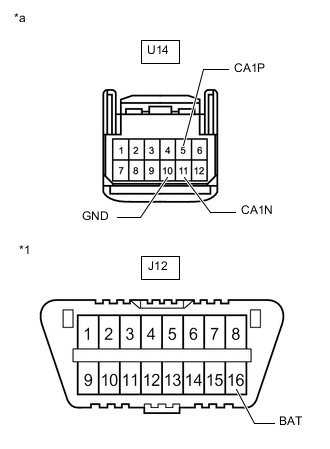
*1 DLC3 *a Front view of wire harness connector
(to Forward Recognition Camera)
Disconnect the U14 forward recognition camera connector.
-
Measure the resistance according to the value(s) in the table below.
-
-
PARKING ASSIST ECU (w/ Panoramic View Monitor System)
Refer to Terminals of ECU for Panoramic View Monitor System for further details.
-
Disconnect the cable from the negative (-) battery terminal.
-
Disconnect the J73 parking assist ECU connector.
-
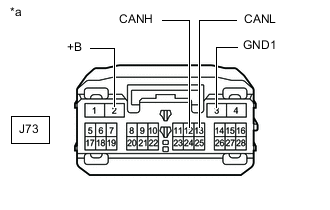
*a Front view of wire harness connector
(to Parking Assist ECU)
Measure the resistance according to the value(s) in the table below.
-
-
ECM (for 2GR-FKS)
Refer to Terminals of ECU for SFI System (for 2GR-FKS) for further details.
-
Click here (w/ Canister Pump Module)
-
Click here (w/o Canister Pump Module)
-
Disconnect the cable from the negative (-) battery terminal.
-
Disconnect the A37 and D2 ECM connectors.

*a Front view of wire harness connector
(to ECM)
- - -
Measure the resistance according to the value(s) in the table below.
-
-
ECM (for 8AR-FTS)
Refer to Terminals of ECU for SFI System (for 8AR-FTS) for further details.
-
Disconnect the cable from the negative (-) battery terminal.
-
Disconnect the A46 and D1 ECM connectors.
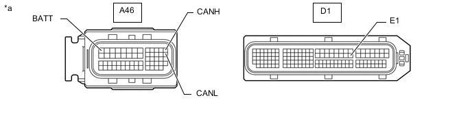
*a Front view of wire harness connector
(to ECM)
- - -
Measure the resistance according to the value(s) in the table below.
-
-
ENGINE STOP AND START ECU (w/ Stop and Start System)
Refer to Terminals of ECU for Stop and Start System for further details.
-
Disconnect the cable from the negative (-) battery terminal.
-
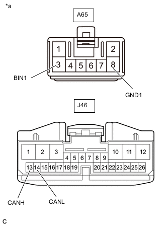
*a Front view of wire harness connector
(to Engine Stop and Start ECU)
Disconnect the A65 and J46 engine stop and start ECU connectors.
-
Measure the resistance according to the value(s) in the table below.
-
-
RADIO RECEIVER ASSEMBLY (w/ Navigation System or 12.3 Inch Display Type Audio and Visual System)
Refer to Terminals of ECU for Navigation System or 12.3 Inch Display Type Audio and Visual System for further details.
-
Click here (w/ Navigation System)
-
Click here (w/ 12.3 Inch Display Type Audio and Visual System)
-
Disconnect the cable from the negative (-) battery terminal.
-
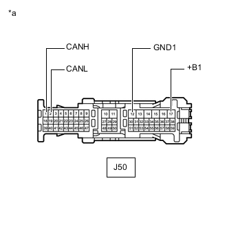
*a Front view of wire harness connector
(to Radio Receiver Assembly)
Disconnect the J50 radio receiver assembly connector.
-
Measure the resistance according to the value(s) in the table below.
-
-
RADIO RECEIVER ASSEMBLY (w/ 8 Inch Display Type Audio and Visual System)
Refer to Terminals of ECU for 8 Inch Display Type Audio and Visual System for further details.
-
Disconnect the cable from the negative (-) battery terminal.
-
Disconnect the J52 and J53 radio receiver assembly connectors.
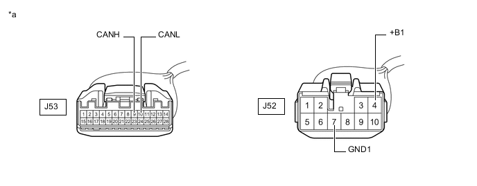
*a Front view of wire harness connector
(to Radio Receiver Assembly)
- - -
Measure the resistance according to the value(s) in the table below.
-
-
TELEMATICS TRANSCEIVER (w/ Manual (SOS) Switch)
Refer to Terminals of ECU for Telematics System for further details.
Click here (for G-BOOK)
Click here (except G-BOOK)
-
Disconnect the cable from the negative (-) battery terminal.
-
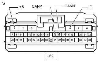
*a Front view of wire harness connector
(to Telematics Transceiver)
Disconnect the J62 telematics transceiver connector.
-
Measure the resistance according to the value(s) in the table below.
-
-
SKID CONTROL ECU (BRAKE ACTUATOR ASSEMBLY)
Refer to Terminals of ECU for Vehicle Stability Control System for further details.
-
Disconnect the cable from the negative (-) battery terminal.
-
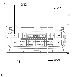
*a Front view of wire harness connector
(to Skid Control ECU (Brake Actuator Assembly))
Disconnect the A41 skid control ECU (brake actuator assembly) connector.
-
Measure the resistance according to the value(s) in the table below.
-
-
POWER STEERING ECU ASSEMBLY
Refer to Terminals of ECU for Power Steering System for further details.
-
Disconnect the cable from the negative (-) battery terminal.
-
Disconnect the J4 and J5 power steering ECU assembly connectors.
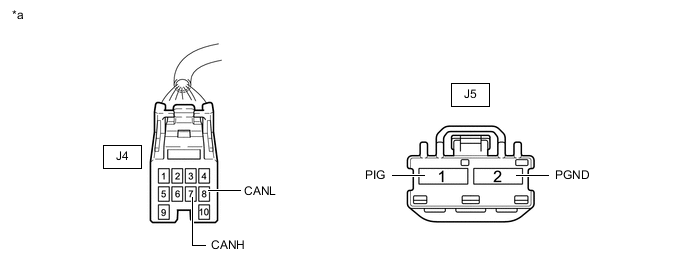
*a Front view of wire harness connector
(to Power Steering ECU Assembly)
- - -
Measure the resistance according to the value(s) in the table below.
-
-
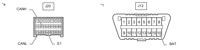
AIRBAG SENSOR ASSEMBLY
Refer to Terminals of ECU for Airbag System for further details.
-
Disconnect the cable from the negative (-) battery terminal.
-
Disconnect the J20 airbag sensor assembly connector.
*1 DLC3 - - *a Front view of wire harness connector
(to Airbag Sensor Assembly)
- - -
Measure the resistance according to the value(s) in the table below.
-
-
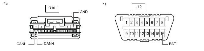
4WD ECU ASSEMBLY (for AWD)
Refer to Terminals of ECU for Dynamic Torque Control AWD System for further details.
-
Disconnect the cable from the negative (-) battery terminal.
-
Disconnect the R10 4WD ECU assembly connector.
*1 DLC3 - - *a Front view of wire harness connector
(to 4WD ECU Assembly)
- - -
Measure the resistance according to the value(s) in the table below.
-
-
TIRE PRESSURE WARNING ECU AND RECEIVER (for Tire Pressure Warning ECU and Receiver Integrated with Electrical Key Receiver)
Refer to Terminals of ECU for Tire pressure Warning System for further details.
-
Disconnect the cable from the negative (-) battery terminal.
-
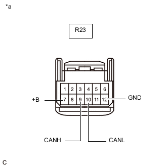
*a Front view of wire harness connector
(to Tire Pressure Warning ECU and Receiver)
Disconnect the R23 tire pressure warning ECU and receiver connector.
-
Measure the resistance according to the value(s) in the table below.
-
-
TIRE PRESSURE WARNING ECU AND RECEIVER (for Tire Pressure Warning ECU and Receiver (Stand Alone) (Roof))
Refer to Terminals of ECU for Tire pressure Warning System for further details.
-
Disconnect the cable from the negative (-) battery terminal.
-

*1 DLC3 *a Front view of wire harness connector
(to Tire Pressure Warning ECU and Receiver)
Disconnect the S54 tire pressure warning ECU and receiver connector.
-
Measure the resistance according to the value(s) in the table below.
-
-
TIRE PRESSURE WARNING ECU AND RECEIVER (for Tire Pressure Warning ECU and Receiver (Stand Alone) (Quarter Panel))
Refer to Terminals of ECU for Tire pressure Warning System for further details.
-
Disconnect the cable from the negative (-) battery terminal.
-
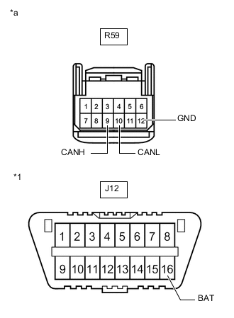
*1 DLC3 *a Front view of wire harness connector
(to Tire Pressure Warning ECU and Receiver)
Disconnect the R59 tire pressure warning ECU and receiver connector.
-
Measure the resistance according to the value(s) in the table below.
-
-
ABSORBER CONTROL ECU (w/ AVS)
Refer to Terminals of ECU for Adaptive Variable Suspension System for further details.
-
Disconnect the cable from the negative (-) battery terminal.
-
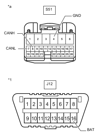
*1 DLC3 *a Front view of wire harness connector
(to Absorber Control ECU)
Disconnect the S51 absorber control ECU connector.
-
Measure the resistance according to the value(s) in the table below.
-
-
COMBINATION METER ASSEMBLY
Refer to Terminals of ECU for Meter / Gauge System for further details.
-
Disconnect the cable from the negative (-) battery terminal.
-
Disconnect the J10 combination meter assembly connector.

*a Front view of wire harness connector
(to Combination Meter Assembly)
- - -
Measure the resistance according to the value(s) in the table below.
-
-
MAIN BODY ECU (MULTIPLEX NETWORK BODY ECU)
Refer to Terminals of ECU for Lighting System for further details.
-
Disconnect the cable from the negative (-) battery terminal.
-
Disconnect the J8 and J9 main body ECU (multiplex network body ECU) connectors.
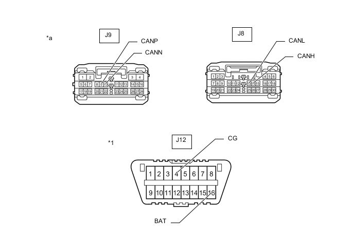
*1 DLC3 - - *a Front view of wire harness connector
(to Main Body ECU (Multiplex Network Body ECU))
- - -
Measure the resistance according to the value(s) in the table below.
-
-
CERTIFICATION ECU (SMART KEY ECU ASSEMBLY)
Refer to Terminals of ECU for Entry and Start System (for Start Function) for further details.
-
Disconnect the cable from the negative (-) battery terminal.
-
Disconnect the J41 certification ECU (smart key ECU assembly) connector.
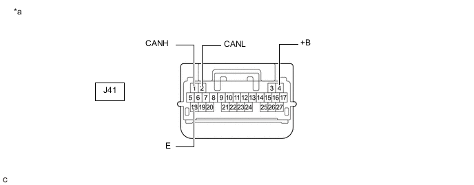
*a Front view of wire harness connector
(to Certification ECU (Smart Key ECU Assembly))
- - -
Measure the resistance according to the value(s) in the table below.
-
-
AIR CONDITIONING AMPLIFIER ASSEMBLY
Refer to Terminals of ECU for Air Conditioning System for further details.
-
Disconnect the cable from the negative (-) battery terminal.
-
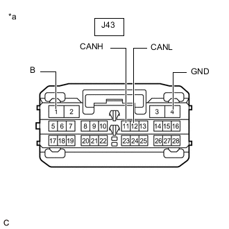
*a Front view of wire harness connector
(to Air Conditioning Amplifier Assembly)
Disconnect the J43 air conditioning amplifier assembly connector.
-
Measure the resistance according to the value(s) in the table below.
-
-
HEADLIGHT ECU SUB-ASSEMBLY LH
Refer to Terminals of ECU for Lighting System for further details.
-
Disconnect the cable from the negative (-) battery terminal.
-
Disconnect the A49 headlight ECU sub-assembly LH connector.
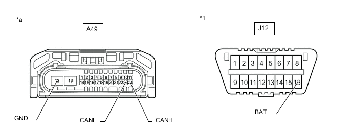
*1 DLC3 - - *a Front view of wire harness connector
(to Headlight ECU Sub-assembly LH)
- - -
Measure the resistance according to the value(s) in the table below.
-
-
OUTER MIRROR CONTROL ECU ASSEMBLY (for LH Side)
Refer to Terminals of ECU for Power Mirror Control System (w/ Memory) for further details.
-
Disconnect the cable from the negative (-) battery terminal.
-
Disconnect the N4 outer mirror control ECU assembly (for LH side) connector.

*a Front view of wire harness connector
(to Outer Mirror Control ECU Assembly (for LH Side))
- - -
Measure the resistance according to the value(s) in the table below.
-
-
OUTER MIRROR CONTROL ECU ASSEMBLY (for RH Side)
Refer to Terminals of ECU for Power Mirror Control System (w/ Memory) for further details.
-
Disconnect the cable from the negative (-) battery terminal.
-
Disconnect the M4 outer mirror control ECU assembly (for RH side) connector.

*a Front view of wire harness connector
(to Outer Mirror Control ECU Assembly (for RH Side))
- - -
Measure the resistance according to the value(s) in the table below.
-
-
POSITION CONTROL ECU AND SWITCH ASSEMBLY LH (w/ Seat Position Memory System)
Refer to Terminals of ECU for Front Power Seat Control System (w/ Memory) for further details.
-
Disconnect the cable from the negative (-) battery terminal.
-
Disconnect the c5 and c6 position control ECU and switch assembly LH connectors.

*a Front view of wire harness connector
(to Position Control ECU and Switch Assembly LH)
- - -
Measure the resistance according to the value(s) in the table below.
-
-
POSITION CONTROL ECU AND SWITCH ASSEMBLY RH (w/ Seat Position Memory System)
Refer to Terminals of ECU for Front Power Seat Control System (w/ Memory) for further details.
-
Disconnect the cable from the negative (-) battery terminal.
-
Disconnect the b16 and b17 position control ECU and switch assembly RH connectors.
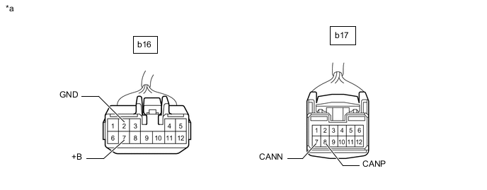
*a Front view of wire harness connector
(to Position Control ECU and Switch Assembly RH)
- - -
Measure the resistance according to the value(s) in the table below.
-
-
MULTIPLEX NETWORK DOOR ECU (w/ Power Back Door System)
Refer to Terminals of ECU for Power Back Door System for further details.
-
Disconnect the cable from the negative (-) battery terminal.
-
Disconnect the Z16 and Z17 multiplex network door ECU connectors.
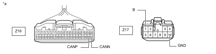
*a Front view of wire harness connector
(to Multiplex Network Door ECU)
- - -
Measure the resistance according to the value(s) in the table below.
-
-
MULTIPLEX TILT AND TELESCOPIC ECU
Refer to Terminals of ECU for Power Tilt and Telescopic Steering Column System for further details.
-
Disconnect the cable from the negative (-) battery terminal.
-
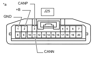
*a Front view of wire harness connector
(to Multiplex Tilt and Telescopic ECU)
Disconnect the J25 multiplex tilt and telescopic ECU connector.
-
Measure the resistance according to the value(s) in the table below.
-
-
OCCUPANT DETECTION ECU (w/ 12.3 Inch Display Type Audio and Visual System)
Refer to Terminals of ECU for Occupant Classification System for further details.
-
Disconnect the cable from the negative (-) battery terminal.
-
Disconnect the A occupant detection ECU connector.
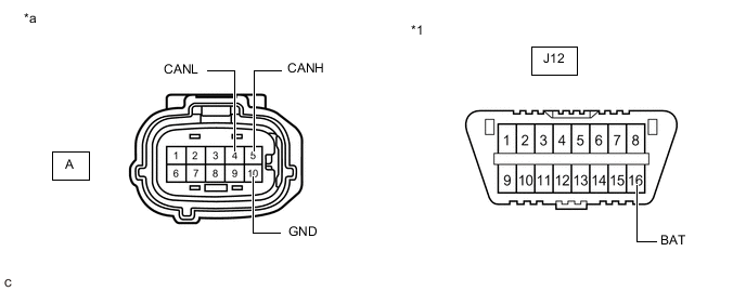
*1 DLC3 - - *a Front view of wire harness connector
(to Occupant Detection ECU)
- - -
Measure the resistance according to the value(s) in the table below.
-