ROOF HEADLINING(w/o Rear No. 2 Seat) REMOVAL
CAUTION / NOTICE / HINT
The necessary procedures (adjustment, calibration, initialization or registration) that must be performed after parts are removed and installed, or replaced during roof headlining removal/installation are shown below.
| Replaced Part or Performed Procedure | Necessary Procedure | Effect/Inoperative Function when Necessary Procedure not Performed | Link |
|---|---|---|---|
| Disconnect cable from negative battery terminal | Memorize steering angle neutral point | LKA/LDA System | |
| Intelligent clearance sonar system*1 | |||
| Pre-crash safety system | |||
| Lighting system (EXT)
|
|||
| Adaptive high beam system | |||
| Drive the vehicle until stop and start control is permitted (approximately 15 to 60 minutes) | Stop and start system | ||
| Memorize steering angle neutral point | Parking assist monitor system (w/ Parallel parking assist function) | ||
| Parking assist monitor system (w/o Parallel parking assist function) | |||
| Panoramic view monitor system | |||
| Initialize back door lock | Power door lock control system | ||
| Reset back door close position | Power back door system |
*1: When performing learning using the GTS.
CAUTION:
Some of these service operations affect the SRS airbag system. Read the precautionary notices concerning the SRS airbag system before servicing.
PROCEDURE
-
REMOVE TONNEAU COVER ASSEMBLY
-
Remove the tonneau cover assembly.
-
-
REMOVE DECK BOARD ASSEMBLY
-
Remove the deck board assembly.
-
-
REMOVE REAR NO. 3 FLOOR BOARD
-
Remove the rear No. 3 floor board.
-
-
REMOVE SPARE WHEEL COVER (for Compact Spare Tire)
-
Remove the spare wheel cover.
-
-
REMOVE REAR DECK FLOOR BOX (w/ Spare Tire)
-
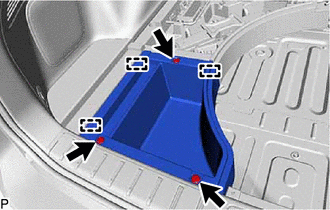
Remove the 3 clips.
-
Disengage the 3 guides to remove the rear deck floor box.
-
-
REMOVE REAR FLOOR CARPET (w/o Spare Tire)
-
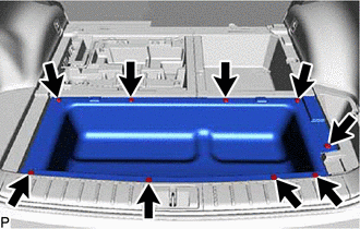
Remove the 9 clips and rear floor carpet.
-
-
REMOVE REAR NO. 4 FLOOR BOARD (except Full Size Spare Tire)
-
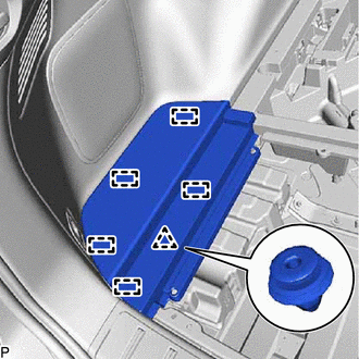
Disengage the clip and 5 guides to remove the rear No. 4 floor board.
-
-
REMOVE REAR NO. 4 FLOOR BOARD (for Full Size Spare Tire)
-
Remove the clip.
-
Disengage the clip and 5 guides to remove the rear No. 4 floor board.
-
-
REMOVE FRONT DECK FLOOR BOX (w/ Spare Tire)
-
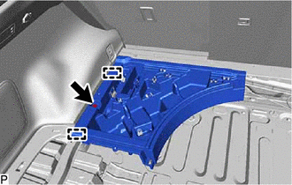
Remove the clip.
-
Disengage the 2 guides to remove the front deck floor box.
-
-
REMOVE DECK FLOOR BOX RH (w/o Spare Tire)
-
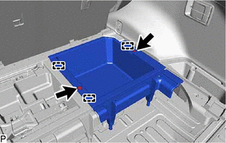
Remove the 2 clips.
-
Disengage the 3 guides to remove the deck floor box RH.
-
-
REMOVE DECK FLOOR BOX LH (w/o Spare Tire)
-
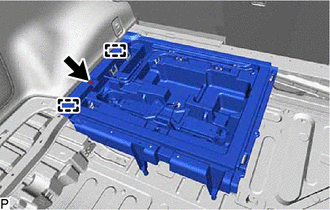
Remove the clip.
-
Disengage the 2 guides to remove the deck floor box LH.
-
-
REMOVE DECK SIDE TRIM BOX RH (except Full Size Spare Tire)
-
Using a clip remover, remove the 2 clips.
-
Disengage the 5 guides to remove the deck side trim box RH.
-
-
REMOVE DECK SIDE TRIM BOX RH (for Full Size Spare Tire)
-
Using a clip remover, remove the 3 clips.
-
Disengage the 5 guides to remove the deck side trim box RH.
-
-
REMOVE REAR FLOOR FINISH PLATE
-

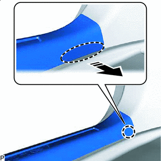
Place Hand Here 
Remove in this Direction Disengage the claw as shown in the illustration.
Tech Tips
Use the same procedure for the RH side and LH side.
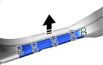
-
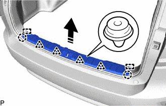
Remove in this Direction Disengage the 2 claws, 4 clips and 2 guides to remove the rear floor finish plate as shown in the illustration.
-
-
REMOVE FRONT DOOR SCUFF PLATE LH
-
Place Hand Here Remove in this Direction Disengage the claw as shown in the illustration.
Tech Tips
Use the same procedure for the front side and rear side.
-
Remove in this Direction Disengage the 8 claws and 2 guides to remove the front door scuff plate LH as shown in the illustration.
-
w/ Illumination:
-
Disconnect the connector.
-
-
-
REMOVE FRONT PILLAR GARNISH LH
-
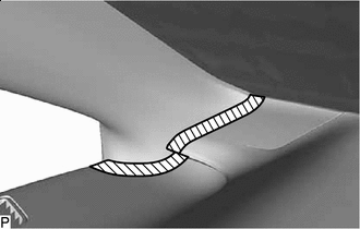

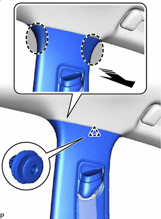
Protective Tape Apply protective tape around the front pillar garnish LH as shown in the illustration.
-
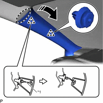
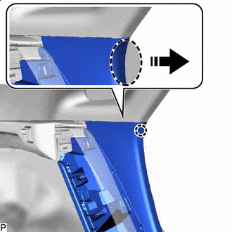
*1 Front Pillar Garnish Clip Place Hand Here Remove in this Direction Pull the upper part of the front pillar garnish LH toward the inside of the cabin to disengage the clip and the front pillar garnish LH from the base of the front pillar garnish clip.
Tech Tips
Let the front pillar garnish LH hang from the front pillar garnish clip.
-
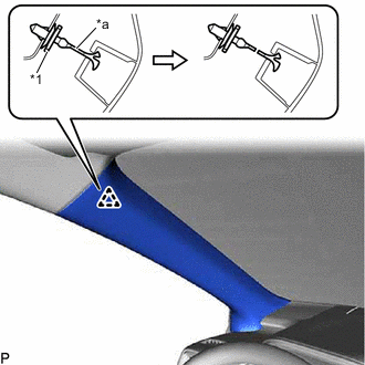
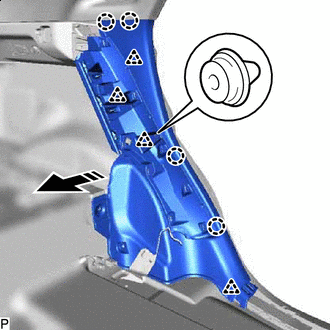
*1 Front Pillar Garnish Clip *a Cut Cut off the front pillar garnish clip as shown in the illustration.
Note
Replace the front pillar garnish clip with a new one.
-
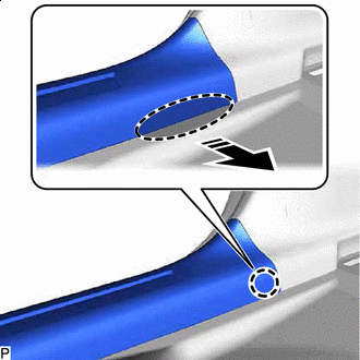
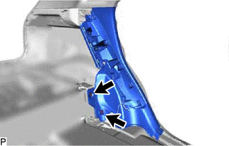
Using a clip remover, remove the front pillar garnish clip from the vehicle body.
-
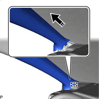
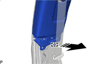
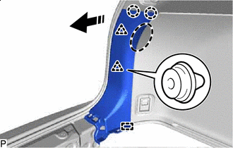
Remove in this Direction Disengage the guide to remove the front pillar garnish LH as shown in the illustration.
-
Remove the clip from the front pillar garnish LH.
-
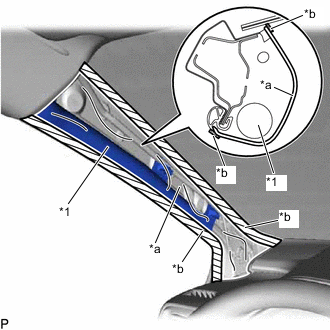
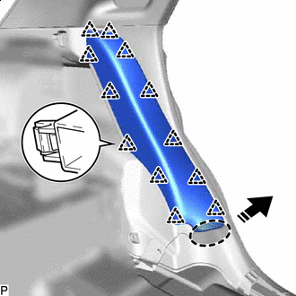
*1 Curtain Shield Airbag Assembly LH *a Protective Cover *b Adhesive Tape Protect the curtain shield airbag assembly LH.
-
Cover the curtain shield airbag assembly LH with a piece of cloth or nylon and secure the edges of the cover with tape as shown in the illustration.
Note
Cover the curtain shield airbag assembly LH with a protective cover as soon as the front pillar garnish LH is removed.
-
-
-
REMOVE REAR DOOR SCUFF PLATE LH
-
Place Hand Here Remove in this Direction Disengage the claw as shown in the illustration.
Tech Tips
Use the same procedure for the front side and rear side.
-
Remove in this Direction Disengage the 8 claws and 2 guides to remove the rear door scuff plate LH as shown in the illustration.
-
-
REMOVE LOWER CENTER PILLAR GARNISH LH
-
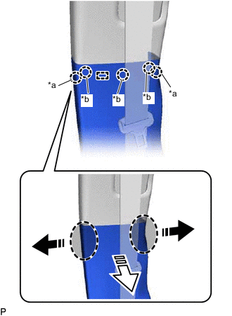
*a Claw (A) *b Claw (B) Place Hand Here Remove in this Direction (1) 
Remove in this Direction (2) Pull the lower center pillar garnish LH in the directions indicated by the arrows (1) shown in the illustration to disengage the 2 claws (A).
-
Pull the lower center pillar garnish LH in the direction indicated by the arrow (2) shown in the illustration to disengage the guide and 3 claws (B).
-
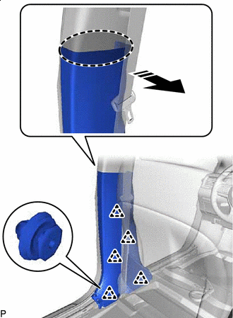
Place Hand Here Remove in this Direction Disengage the 5 clips to remove the lower center pillar garnish LH as shown in the illustration.
-
-
DISCONNECT FRONT SEAT OUTER BELT ASSEMBLY LH
-
REMOVE CENTER PILLAR GARNISH LH
-
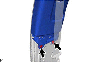
Using a clip remover, remove the 2 clips.
-
Place Hand Here Remove in this Direction Disengage the clip as shown in the illustration.
-
Remove in this Direction Disengage the guide to remove the center pillar garnish LH as shown in the illustration.
-
Remove the clip from the center pillar garnish LH.
-
-
REMOVE FRONT DOOR SCUFF PLATE RH
Tech Tips
Use the same procedure as for the LH side.
-
REMOVE FRONT PILLAR GARNISH RH
Tech Tips
Use the same procedure as for the LH side.
-
REMOVE REAR DOOR SCUFF PLATE RH
Tech Tips
Use the same procedure as for the LH side.
-
REMOVE LOWER CENTER PILLAR GARNISH RH
Tech Tips
Use the same procedure as for the LH side.
-
DISCONNECT FRONT SEAT OUTER BELT ASSEMBLY RH
Tech Tips
Use the same procedure as for the LH side.
-
REMOVE CENTER PILLAR GARNISH RH
Tech Tips
Use the same procedure as for the LH side.
-
REMOVE REAR SEAT ASSEMBLY LH
-
REMOVE REAR SEAT ASSEMBLY RH
-
REMOVE UPPER QUARTER TRIM PAD LH
-
Place Hand Here Remove in this Direction Disengage the 12 clips to remove the upper quarter trim pad LH as shown in the illustration.
-
-
REMOVE REAR SEAT SIDE GARNISH LH
-
Using a clip remover, remove the 2 clips.
-
Place Hand Here Remove in this Direction Disengage the claw as shown in the illustration.
-
Remove in this Direction Disengage the 4 claws and 4 clips to remove the rear seat side garnish LH as shown in the illustration.
-
-
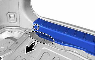
REMOVE REAR FLOOR FINISH SIDE PLATE LH
-
Place Hand Here Remove in this Direction Disengage the 2 claws, 2 clips and guide to remove the rear floor finish side plate LH.
-
-
REMOVE NO. 1 LUGGAGE COMPARTMENT TRIM HOOK (for LH Side)
-
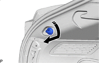
Remove in this Direction Turn the No. 1 luggage compartment trim hook as shown in the illustration to remove it.
-
-
REMOVE ROPE HOOK ASSEMBLY (for LH Side)
-
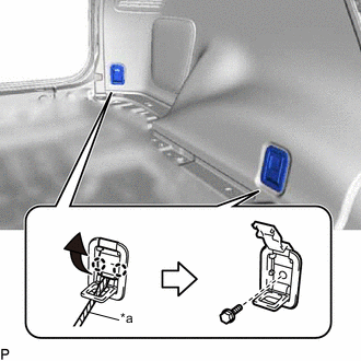
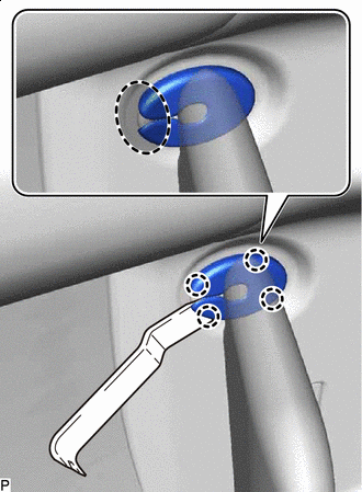
*a Protective Tape Using a screwdriver with its tip wrapped with protective tape, disengage the 4 claws and open each cover.
-
Remove the 2 bolts and 2 rope hook assemblies.
-
-
REMOVE NO. 1 LUGGAGE COMPARTMENT LIGHT ASSEMBLY (for LH Side)
-
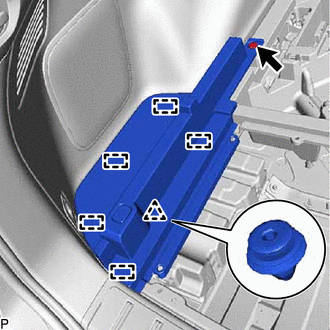
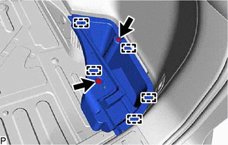
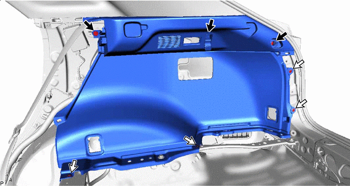
REMOVE DECK TRIM SIDE PANEL ASSEMBLY LH
-
Remove the 3 bolts.
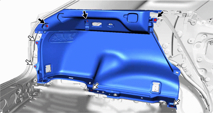

Bolt 
Clip -
Using a clip remover, remove the 4 clips.
-
Place Hand Here Remove in this Direction Disengage the 5 claws as shown in the illustration.
-
Disconnect the connector to remove the deck trim side panel assembly LH.
-
-
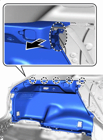
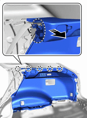
REMOVE ROOF SIDE INNER GARNISH ASSEMBLY LH
-
Disengage the 9 clips to remove the roof side inner garnish assembly LH.
Place Hand Here Remove in this Direction -
Remove the 9 clips from the roof side inner garnish assembly LH.
-
-
REMOVE UPPER QUARTER TRIM PAD RH
Tech Tips
Use the same procedure as for the LH side.
-
REMOVE REAR SEAT SIDE GARNISH RH
Tech Tips
Use the same procedure as for the LH side.
-
REMOVE REAR FLOOR FINISH SIDE PLATE RH
Tech Tips
Use the same procedure as for the LH side.
-
REMOVE NO. 1 LUGGAGE COMPARTMENT TRIM HOOK (for RH Side)
-
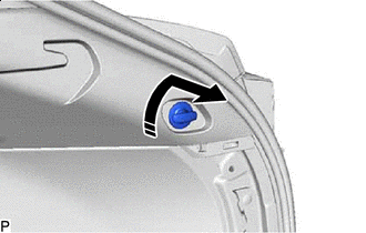
Remove in this Direction Turn the No. 1 luggage compartment trim hook as shown in the illustration to remove it.
-
-
REMOVE ROPE HOOK ASSEMBLY (for RH Side)
Tech Tips
Use the same procedure as for the LH side.
-
REMOVE NO. 1 LUGGAGE COMPARTMENT LIGHT ASSEMBLY (for RH Side)
-
REMOVE RECLINING REMOTE CONTROL BEZEL RH (w/o Rear Power Seat System)
-
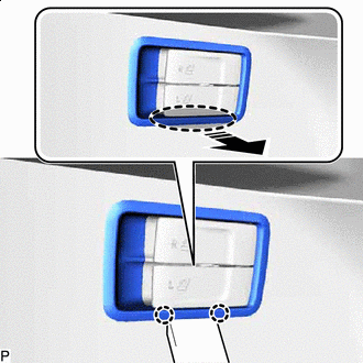
Insert Moulding Remover Here Remove in this Direction Using a moulding remover, disengage the 2 claws as shown in the illustration.
-
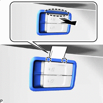
Insert Moulding Remover Here Remove in this Direction Using a moulding remover, disengage the 2 claws as shown in the illustration.
-
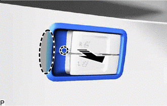
Place Hand Here Remove in this Direction Disengage the claw to remove the reclining remote control bezel RH.
-
-
REMOVE FOLD SEAT SWITCH ASSEMBLY (w/ Rear Power Seat System)
-
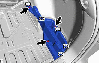
REMOVE DECK TRIM SIDE PANEL ASSEMBLY RH
-
Remove the 3 bolts.
Bolt Clip -
Using a clip remover, remove the 4 clips.
-
Place Hand Here Remove in this Direction Disengage the 5 claws to remove the deck trim side panel assembly RH as shown in the illustration.
-
-
REMOVE ROOF SIDE INNER GARNISH ASSEMBLY RH
Tech Tips
Use the same procedure as for the LH side.
-
REMOVE ROOF CONSOLE BOX ASSEMBLY
-
REMOVE SPOT LIGHT ASSEMBLY
-
REMOVE RAIN SENSOR COVER (w/ Rain Sensor)
-
REMOVE RAIN SENSOR (w/ Rain Sensor)
-
REMOVE INNER REAR VIEW MIRROR STAY HOLDER COVER (w/ Inner Rear View Mirror Stay Holder Cover)
-
REMOVE NO. 2 FORWARD RECOGNITION COVER (w/ Lexus Safety System+)
-
REMOVE NO. 1 FORWARD RECOGNITION COVER (w/ Lexus Safety System+)
-
REMOVE ASSIST GRIP ASSEMBLY
Tech Tips
Use the same procedure for all assist grip assemblies.
-
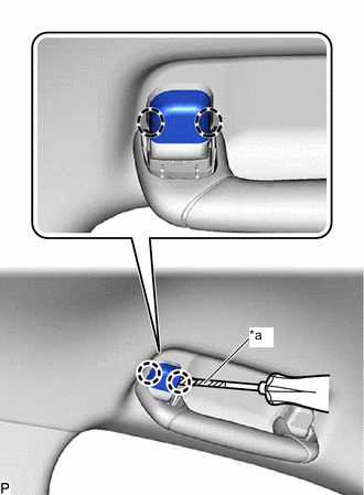
*a Protective Tape Insert Screwdriver Here Using a screwdriver with its tip wrapped with protective tape, disengage the 2 claws and remove the assist grip cover LH.
Tech Tips
Use the same procedure for the RH side and LH side.
-
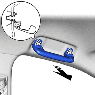
Remove in this Direction Disengage the 2 clips to remove the assist grip assembly.
-
Remove the 2 clips from the vehicle body.
-
-
REMOVE REAR ASSIST GRIP ASSEMBLY LH
Tech Tips
Use the same procedure as for the assist grip assembly.
-
REMOVE REAR ASSIST GRIP ASSEMBLY RH
Tech Tips
Use the same procedure as for the assist grip assembly.
-
REMOVE VISOR BRACKET COVER (for LH Side)
-
Insert Moulding Remover Here Using a moulding remover, disengage the 4 claws and remove the visor bracket cover as shown in the illustration.
-
-
REMOVE VISOR ASSEMBLY LH
-
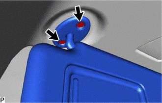
Remove the 2 screws.
-
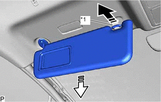
*1 Visor Holder Remove in this Direction (1) Remove in this Direction (2) Pull the visor assembly LH in the direction indicated by the arrow (1) shown in the illustration to disconnect it from the visor holder.
-
Pull the visor assembly LH in the direction indicated by the arrow (2) shown in the illustration to remove it.
-
-
REMOVE VISOR HOLDER (for LH Side)
-
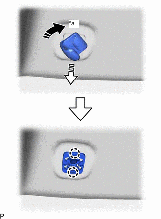
*a 45° Remove in this Direction (1) Remove in this Direction (2) Turn the visor holder approximately 45° and pull it out as indicated by the arrows, in the order shown in the illustration.
-
Disengage the 2 claws to remove the visor holder.
-
-
REMOVE VISOR BRACKET COVER (for RH Side)
Tech Tips
Use the same procedure as for the LH side.
-
REMOVE VISOR ASSEMBLY RH
Tech Tips
Use the same procedure as for the LH side.
-
REMOVE VISOR HOLDER (for RH Side)
Tech Tips
Use the same procedure as for the LH side.
-
REMOVE ROOF HEADLINING ASSEMBLY
-
for Windshield Glass Side:
-
Disconnect each connector.
-
-
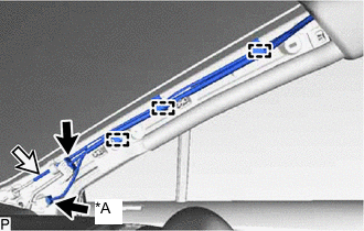
for Front Pillar LH Side:
-
Remove the protective cover.
-
Disengage the 4 clamps.
-
Disconnect the 3 connectors.
-
Install the protective cover.
-
-
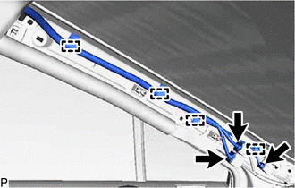
for Front Pillar RH Side:
-
Remove the protective cover.
-
Disengage the 3 clamps.
-
*A w/ Telematics Transceiver except G-BOOK Connector Washer Hose Assembly Disconnect each connector and the washer hose assembly.
Tech Tips
Use a container to collect the windshield washer fluid.
-
Install the protective cover.
-
-
for Rear Pillar RH Side:
-
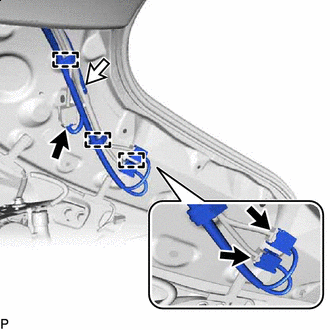
Connector Washer Hose Assembly Disengage each clamp.
-
Disconnect each connector and the washer hose assembly.
Tech Tips
Use a container to collect the windshield washer fluid.
-
-
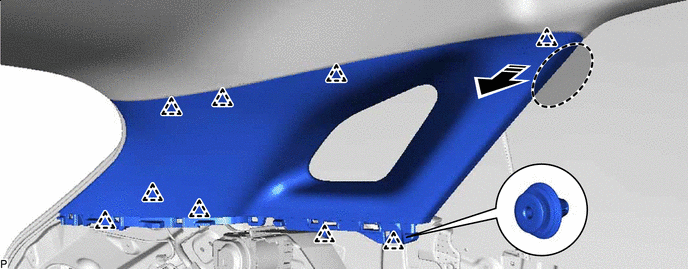
for Standard Roof:
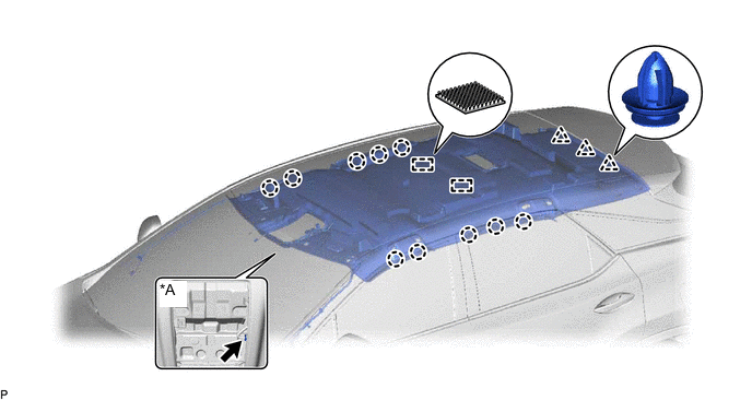
*A w/ Television Antenna - -
-
w/ Television Antenna:
-
Disconnect the connector.
-
-
Disengage the 10 claws, 3 clips and 2 fasteners.
-
-
for Sliding Roof:
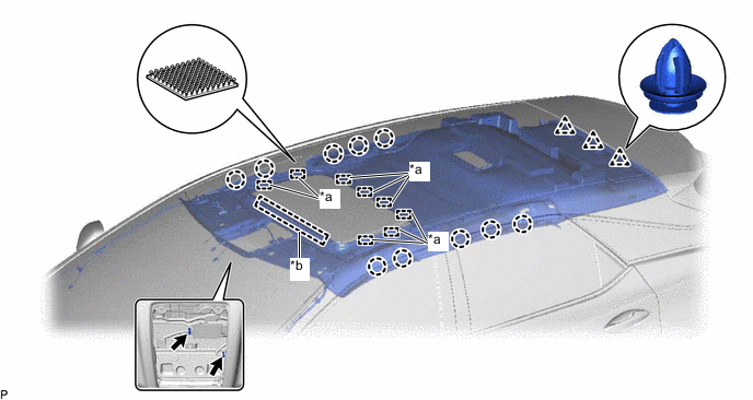
*a Fastener *b Guide
-
Disconnect each connector.
-
Disengage the 10 claws, 3 clips, 8 fasteners and guide.
-
-
for Panoramic Moon Roof:
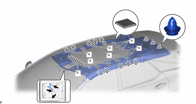
*a Fastener *b Guide
-
Disconnect each connector.
-
Disengage the 10 claws, 3 clips, 13 fasteners and guide.
-
-
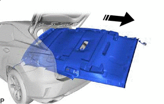
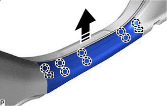
Remove in this Direction Remove the roof headlining assembly from the vehicle through the back door as shown in the illustration.
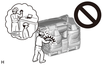
Note
Do not damage the roof headlining assembly or vehicle interior.
-