REAR POWER OUTLET SOCKET(w/o Rear No. 2 Seat) REMOVAL
CAUTION / NOTICE / HINT
The necessary procedures (adjustment, calibration, initialization, or registration) that must be performed after parts are removed and installed, or replaced during rear power outlet socket removal/installation are shown below.
| Replaced Part or Performed Procedure | Necessary Procedure | Effect/Inoperative Function when Necessary Procedure not Performed | Link |
|---|---|---|---|
| Disconnect cable from negative battery terminal | Memorize steering angle neutral point | LKA/LDA System | |
| Intelligent clearance sonar system*1 | |||
| Pre-Crash Safety System | |||
| Lighting System (EXT)
|
|||
| Adaptive High Beam System | |||
| Drive the vehicle until stop and start control is permitted (approximately 15 to 60 minutes) | Stop and start system | ||
| Memorize steering angle neutral point | Parking Assist Monitor System (w/ Parallel Parking Assist Function) | ||
| Parking Assist Monitor System (w/o Parallel Parking Assist Function) | |||
| Panoramic View Monitor System | |||
| Initialize back door lock | Power door lock control system | ||
| Reset back door close position | Power back door system |
Click here Click here
CAUTION:
Some of these service operations affect the SRS airbag system. Read the precautionary notices concerning the SRS airbag system before servicing.
PROCEDURE
-
REMOVE TONNEAU COVER ASSEMBLY
-
REMOVE DECK BOARD ASSEMBLY
-
REMOVE SPARE WHEEL COVER (for Compact Spare Tire)
-
REMOVE REAR NO. 3 FLOOR BOARD
-
REMOVE DECK SIDE TRIM BOX RH (except Full Size Spare Tire)
-
REMOVE DECK SIDE TRIM BOX RH (for Full Size Spare Tire)
-
REMOVE REAR DECK FLOOR BOX (w/ Spare Tire)
-
REMOVE REAR FLOOR CARPET (w/o Spare Tire)
-
REMOVE REAR NO. 4 FLOOR BOARD (except Full Size Spare Tire)
-
REMOVE REAR NO. 4 FLOOR BOARD (for Full Size Spare Tire)
-
REMOVE FRONT DECK FLOOR BOX (w/ Spare Tire)
-
REMOVE DECK FLOOR BOX RH (w/o Spare Tire)
-
REMOVE DECK FLOOR BOX LH (w/o Spare Tire)
-
REMOVE REAR FLOOR FINISH PLATE
-
REMOVE REAR DOOR SCUFF PLATE LH
-
REMOVE REAR SEAT ASSEMBLY LH
-
REMOVE UPPER QUARTER TRIM PAD LH
-
REMOVE REAR SEAT SIDE GARNISH LH
-
REMOVE REAR FLOOR FINISH SIDE PLATE LH
-
REMOVE NO. 1 LUGGAGE COMPARTMENT TRIM HOOK
-
REMOVE ROPE HOOK ASSEMBLY
-
REMOVE NO. 1 LUGGAGE COMPARTMENT LIGHT ASSEMBLY
-
REMOVE DECK TRIM SIDE PANEL ASSEMBLY LH
-
REMOVE REAR NO. 1 POWER OUTLET SOCKET ASSEMBLY
-
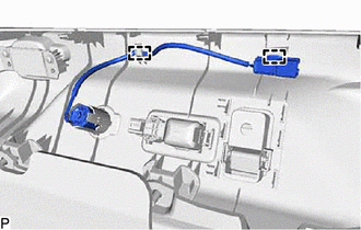
Disengage the 2 clamps.
-
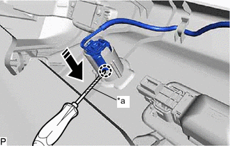
*a Protective Tape 
Remove in this Direction Using a screwdriver with its tip wrapped with protective tape, disengage the claw and remove the rear No. 1 power outlet socket assembly as shown in the illustration.
-
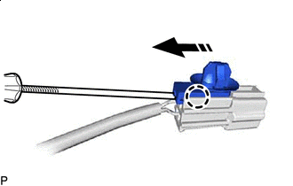
Remove in this Direction Using a screwdriver, disengage the claw and remove the clamp from the rear No. 1 power outlet socket assembly as shown in the illustration.
-
-
REMOVE REAR POWER OUTLET SOCKET COVER
-
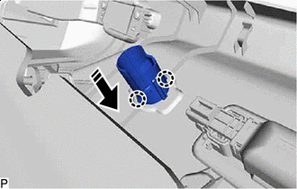
Remove in this Direction Disengage the 2 claws and remove the rear power outlet socket cover as shown in the illustration.
-