REAR AIR CONDITIONING UNIT INSTALLATION
PROCEDURE
-
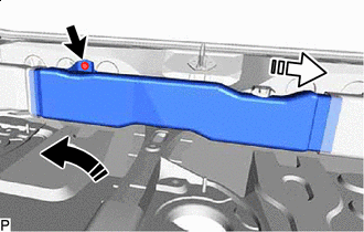
INSTALL DRAIN COOLER HOSE
-
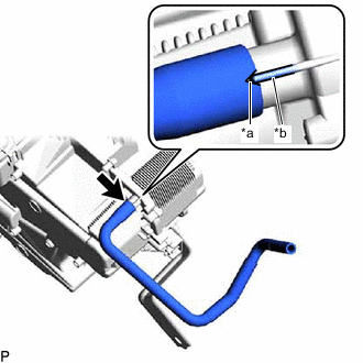
*a Hose Notch *b Rib Align the hose notch with the rib as shown in the illustration and install the drain cooler hose to the rear cooling unit assembly.
-
-
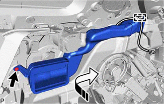
INSTALL AIR CONDITIONING TUBE AND ACCESSORY ASSEMBLY
-
Remove the vinyl tape from the air conditioning tube and accessory assembly and rear cooling unit expansion valve.
-
Sufficiently apply compressor oil to 2 new O-rings and the fitting surface of the air conditioning tube and accessory assembly.
Compressor Oil ND-OIL 8 or equivalent -
Install the 2 O-rings to the air conditioning tube and accessory assembly.
Note
Keep the O-rings and O-ring fitting surfaces free of foreign matter.
-
Connect the air conditioning tube and accessory assembly.
-
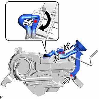
Rotate the hook connector as shown in the illustration.
-
Install the bolt.
- Torque:
- 9.8 N*m { 100 kgf*cm, 87 in.*lbf }
-
Install the air conditioning tube and accessory assembly with the 3 screws.
-
-
INSTALL NO. 1 COOLING UNIT PACKING
-
Install a new No. 1 cooling unit packing.
-
-
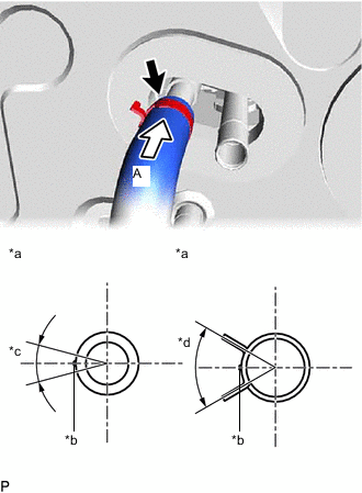
INSTALL WATER PIPE AND HOSE SUB-ASSEMBLY A
-
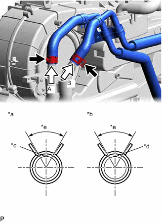
*a View A *b View B *c Marking (Yellow) *d Marking (White) *e Clip Installation Angle (60°) Connect the water pipe and hose sub-assembly A and engage the 2 clips within the area shown in the illustration.
Note
Do not apply excessive force to the water pipe and hose sub-assembly A.
-
Install the water pipe and hose sub-assembly A with the bolt and screw.
- Torque:
- Bolt
- 9.8 N*m { 100 kgf*cm, 87 in.*lbf }
-
-
INSTALL REAR AIR DUCT (w/ Rear Air Duct)
-
Install the rear air duct with the 3 screws.
-
-
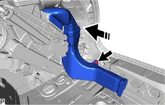
INSTALL REAR AIR CONDITIONING UNIT ASSEMBLY
-
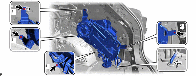
Engage the guide as shown in the illustration.
-
Install the rear air conditioning unit assembly with the 4 bolts.
- Torque:
- 9.8 N*m { 100 kgf*cm, 87 in.*lbf }
Tech Tips
Tighten the bolts in the order shown in the illustration.
-
Connect the drain cooler hose.
-
Engage each clamp.
-
Connect each connector.
-
-
INSTALL REAR NO. 5 AIR DUCT
-

Install in this Direction (1) 
Install in this Direction (2) Connect the rear No. 5 air duct as shown in the illustration.
-
Install the rear No. 5 air duct with the clip.
-
-
INSTALL REAR NO. 6 AIR DUCT
-
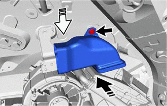
Install in this Direction Connect the rear No. 6 air duct as shown in the illustration.
-
Install the rear No. 6 air duct with the clip.
-
-
INSTALL REAR NO. 7 AIR DUCT
-
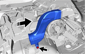
Install in this Direction Connect the rear No. 7 air duct as shown in the illustration.
-
Install the rear No. 7 air duct with the clip.
-
-
INSTALL REAR NO. 1 SIDE AIR DUCT
-
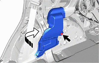
Install in this Direction Connect the rear No. 1 side air duct as shown in the illustration.
-
Install the rear No. 1 side air duct with the clip.
-
-
INSTALL REAR NO. 2 SIDE AIR DUCT
-
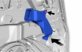
Install in this Direction Connect the rear No. 2 side air duct as shown in the illustration.
-
Install the rear No. 2 side air duct with the clip.
-
Engage the clamp.
-
-
INSTALL REAR NO. 3 SIDE AIR DUCT
-
Install in this Direction Connect the rear No. 3 side air duct as shown in the illustration.
-
Install the rear No. 3 side air duct with the clip.
-
-
INSTALL COOLER PLATE
-
Engage the 2 claws to install the cooler plate.
-
-
INSTALL REAR NO. 4 SIDE AIR DUCT
-
Install in this Direction (1) Install in this Direction (2) Connect the rear No. 4 side air duct as shown in the illustration.
-
Install the rear No. 4 side air duct with the clip.
-
-
INSTALL ROOF SIDE INNER GARNISH ASSEMBLY RH
-
CONNECT REAR NO. 2 SEAT OUTER BELT ASSEMBLY RH
-
INSTALL DECK TRIM SIDE PANEL ASSEMBLY RH
-
INSTALL NO. 1 LUGGAGE COMPARTMENT LIGHT ASSEMBLY
-
INSTALL ROPE HOOK ASSEMBLY
-
INSTALL NO. 1 LUGGAGE COMPARTMENT TRIM HOOK
-
INSTALL REAR SEAT SIDE GARNISH RH
-
INSTALL FRONT DECK SIDE TRIM COVER RH
-
INSTALL REAR SEAT OUTER TRACK BRACKET COVER RH
-
INSTALL REAR DOOR INSIDE SCUFF PLATE RH
-
INSTALL REAR DOOR SCUFF PLATE RH
-
INSTALL REAR FLOOR FINISH PLATE
-
INSTALL REAR NO. 2 SEAT ASSEMBLY
-
CONNECT AIR CONDITIONING HOSE AND ACCESSORY
-
*a View A *b Marking (Yellow) *c Outlet Heater Water Hose Installation Angle (30°) *d Clip Installation Angle (60°) Connect the outlet heater water hose with the marking within the area shown in the illustration.
Note
Do not apply excessive force to the outlet heater water hose.
-
Engage the clip within the area shown in the illustration.
-
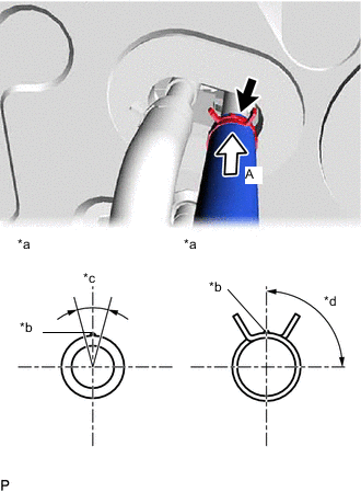
*a View A *b Marking (White) *c Inlet Heater Water Hose Installation Angle (30°) *d Clip Installation Angle (90°) Connect the inlet heater water hose with the marking within the area shown in the illustration.
Note
Do not apply excessive force to the inlet heater water hose.
-
Engage the clip within the area shown in the illustration.
-
Remove the vinyl tape from the liquid tube.
-
Sufficiently apply compressor oil to a new O-ring and the fitting surface of the liquid tube.
Compressor Oil ND-OIL 8 or equivalent -
Install the O-ring to the liquid tube.
Note
Keep the O-ring and O-ring fitting surface free of foreign matter.
-
Connect the liquid tube.
-
Remove the vinyl tape from the suction tube.
-
Sufficiently apply compressor oil to a new O-ring and the fitting surface of the suction tube.
Compressor Oil ND-OIL 8 or equivalent -
Install the O-ring to the suction tube.
Note
Keep the O-ring and O-ring fitting surface free of foreign matter.
-
Connect the suction tube.
-
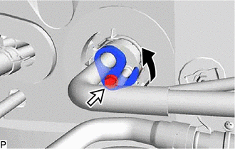
Rotate the hook connector as shown in the illustration.
-
Insert the tube joint into the fitting hole securely and install the bolt.
- Torque:
- 9.8 N*m { 100 kgf*cm, 87 in.*lbf }
-
-
INSTALL NO. 1 LUGGAGE COMPARTMENT SIDE COVER PROTECTOR
-
Install the No. 1 luggage compartment side cover protector with the 3 clips and bolt.
-
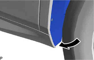
Move the rear wheel house liner RH to its original position as shown in the illustration.
-
Install the 2 screws and a new grommet.
-
-
ADD ENGINE COOLANT
-
INSPECT FOR COOLANT LEAK
-
CHARGE AIR CONDITIONING SYSTEM WITH REFRIGERANT
-
WARM UP ENGINE
-
INSPECT FOR REFRIGERANT LEAK
-
INITIALIZATION SERVO MOTOR