REAR AIR CONDITIONING UNIT REMOVAL
CAUTION / NOTICE / HINT
The necessary procedures (adjustment, calibration, initialization or registration) that must be performed after parts are removed and installed, or replaced during rear air conditioning unit removal/installation are shown below.
| Replaced Part or Performed Procedure | Necessary Procedure | Effect/Inoperative Function when Necessary Procedure not Performed | Link |
|---|---|---|---|
| Disconnect cable from negative battery terminal | Memorize steering angle neutral point | LKA/LDA System | |
| Intelligent clearance sonar system*1 | |||
| Pre-crash safety system | |||
| Lighting system (EXT)
|
|||
| Adaptive high beam system | |||
| Drive the vehicle until stop and start control is permitted (approximately 15 to 60 minutes) | Stop and start system | ||
| Memorize steering angle neutral point | Parking assist monitor system (w/ Parallel parking assist function) | ||
| Parking assist monitor system (w/ Parallel parking assist function) | |||
| Panoramic view monitor system | |||
| Initialize back door lock | Power door lock control system | ||
| Reset back door close position | Power back door system | ||
| Removal/installation of the spiral cable with sensor sub-assembly |
|
Parking assist monitor system (w/ Parallel parking assist function) | Click here for Initialization Click here for Calibration |
| Parking assist monitor system (w/o parallel parking assist function) | Click here for Initialization Click here for Calibration |
||
| Steering angle neutral point (Initialize panoramic view monitor system) | Panoramic view monitor system | Click here for Initialization Click here for Calibration |
|
| Steering angle neutral point (Initialize intelligent clearance sonar system) | Intelligent clearance sonar system | ||
|
Initialize servo motor (Air conditioning system) | DTCs are stored |
Click here Click here
Note
Make sure to select foot mode before removing the rear cooling unit assembly.
PROCEDURE
-
RECOVER REFRIGERANT FROM REFRIGERATION SYSTEM
-
DRAIN ENGINE COOLANT
-
REMOVE NO. 1 LUGGAGE COMPARTMENT SIDE COVER PROTECTOR
-
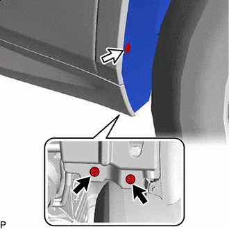

Screw 
Grommet Remove the 2 screws and grommet.
-
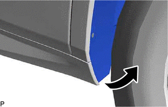
Turn back the rear wheel house liner RH as shown in the illustration.
-
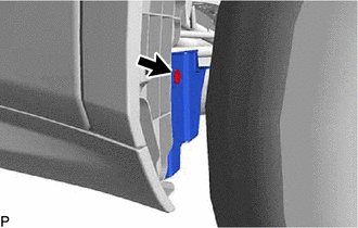
Remove the clip.
-
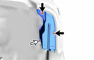
Clip Bolt Remove the 2 clips, bolt and No. 1 luggage compartment side cover protector.
-
-
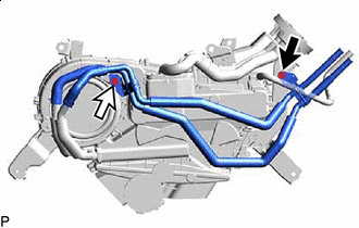
DISCONNECT AIR CONDITIONING HOSE AND ACCESSORY
-
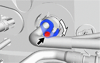
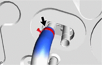
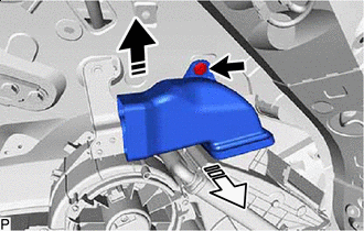
Remove the bolt and rotate the hook connector as shown in the illustration.
-
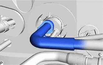
Disconnect the suction tube.
-
Remove the O-ring from the suction tube.
Note
Seal the openings of the disconnected parts using vinyl tape to prevent entry of moisture and foreign matter.
-
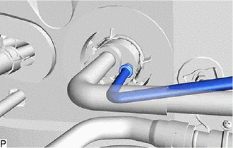
Disconnect the liquid tube.
-
Remove the O-ring from the liquid tube.
Note
Seal the openings of the disconnected parts using vinyl tape to prevent entry of moisture and foreign matter.
-
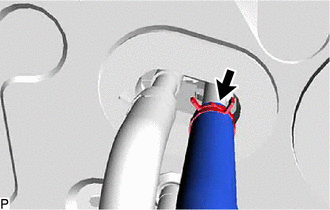
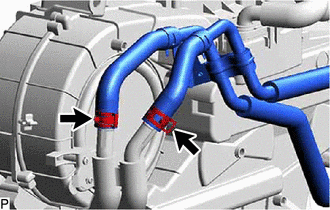
Using pliers, grip the claws of the clip and slide the clip to disconnect the inlet heater water hose.
Note
-
Do not apply excessive force to the inlet heater water hose.
-
Prepare a drain pan or cloth in case the coolant leaks.
-
-
Using pliers, grip the claws of the clip and slide the clip to disconnect the outlet heater water hose.
Note
-
Do not apply excessive force to the outlet heater water hose.
-
Prepare a drain pan or cloth in case the coolant leaks.
-
-
-
REMOVE REAR NO. 2 SEAT ASSEMBLY
-
REMOVE REAR FLOOR FINISH PLATE
-
REMOVE REAR DOOR SCUFF PLATE RH
-
REMOVE REAR DOOR INSIDE SCUFF PLATE RH
-
REMOVE REAR SEAT OUTER TRACK BRACKET COVER RH
-
REMOVE FRONT DECK SIDE TRIM COVER RH
-
REMOVE REAR SEAT SIDE GARNISH RH
-
REMOVE NO. 1 LUGGAGE COMPARTMENT TRIM HOOK
-
REMOVE ROPE HOOK ASSEMBLY
-
REMOVE NO. 1 LUGGAGE COMPARTMENT LIGHT ASSEMBLY
-
REMOVE DECK TRIM SIDE PANEL ASSEMBLY RH
-
DISCONNECT REAR NO. 2 SEAT OUTER BELT ASSEMBLY RH
-
REMOVE ROOF SIDE INNER GARNISH ASSEMBLY RH
-
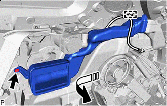
REMOVE REAR NO. 4 SIDE AIR DUCT
-

Remove in this Direction (1) 
Remove in this Direction (2) Remove the clip.
-
Remove the rear No. 4 side air duct as shown in the illustration.
-
-
REMOVE COOLER PLATE
-
Disengage the 2 claws to remove the cooler plate.
-
-
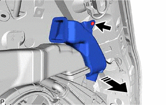
REMOVE REAR NO. 3 SIDE AIR DUCT
-
Remove in this Direction Remove the clip.
-
Remove the rear No. 3 side air duct as shown in the illustration.
-
-
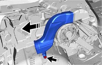
REMOVE REAR NO. 2 SIDE AIR DUCT
-
Remove in this Direction Disengage the clamp.
-
Remove the clip.
-
Remove the rear No. 2 side air duct as shown in the illustration.
-
-
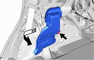
REMOVE REAR NO. 1 SIDE AIR DUCT
-
Remove in this Direction Remove the clip.
-
Remove the rear No. 1 side air duct as shown in the illustration.
-
-
REMOVE REAR NO. 7 AIR DUCT
-
Remove in this Direction Remove the clip.
-
Remove the rear No. 7 air duct as shown in the illustration.
-
-
REMOVE REAR NO. 6 AIR DUCT
-
Remove in this Direction Remove the clip.
-
Remove the rear No. 6 air duct as shown in the illustration.
-
-
REMOVE REAR NO. 5 AIR DUCT
-
Remove in this Direction (1) Remove in this Direction (2) Remove the clip.
-
Remove the rear No. 5 air duct as shown in the illustration.
-
-
REMOVE REAR AIR CONDITIONING UNIT ASSEMBLY
-
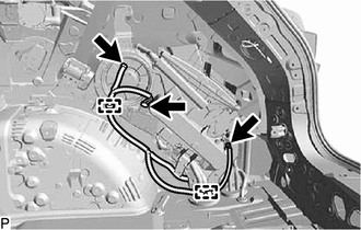
Disconnect each connector.
-
Disengage each clamp.
-
Disconnect the drain cooler hose.
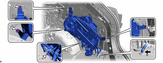
-
Remove the 4 bolts.
-
Disengage the guide and remove the rear air conditioning unit assembly.
-
-
REMOVE REAR AIR DUCT (w/ Rear Air Duct)
-
Remove the 3 screws and rear air duct.
-
-
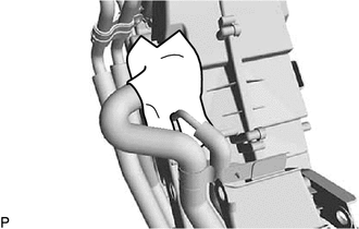
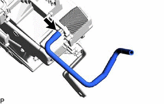
REMOVE WATER PIPE AND HOSE SUB-ASSEMBLY A
-
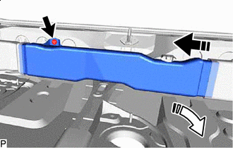
Bolt Screw Remove the bolt and screw.
-
Slide the 2 clips and disconnect the water pipe and hose sub-assembly A.
Note
-
Do not apply excessive force to the water pipe and hose sub-assembly A.
-
Prepare a drain pan or cloth in case the coolant leaks.
-
-
-
REMOVE NO. 1 COOLING UNIT PACKING
-
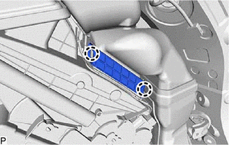
Remove the No. 1 cooling unit packing.
-
-
REMOVE AIR CONDITIONING TUBE AND ACCESSORY ASSEMBLY
-
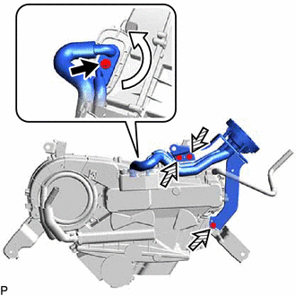
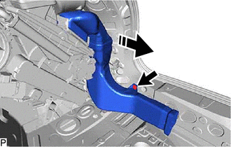
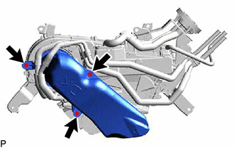
Remove the bolt and rotate the hook connector as shown in the illustration.
-
Remove the 3 screws and air conditioning tube and accessory assembly.
-
Remove the 2 O-rings from the rear cooling unit expansion valve.
Note
Seal the openings of the disconnected parts using vinyl tape to prevent entry of moisture and foreign matter.
-
-
REMOVE DRAIN COOLER HOSE
-
Remove the drain cooler hose from the rear cooling unit assembly.
-