BLOWER UNIT REMOVAL
CAUTION / NOTICE / HINT
The necessary procedures (adjustment, calibration, initialization or registration) that must be performed after parts are removed and installed, or replaced during blower unit removal/installation are shown below.
| Replaced Part or Performed Procedure | Necessary Procedure | Effect/Inoperative Function when Necessary Procedure not Performed | Link |
|---|---|---|---|
| Disconnect cable from negative battery terminal | Memorize steering angle neutral point | LKA/LDA System | |
| Pre-crash safety system | |||
| Lighting system (EXT)
|
|||
| Adaptive high beam system | |||
| Drive the vehicle until stop and start control is permitted (approximately 15 to 60 minutes) | Stop and start system | ||
| Memorize steering angle neutral point | Parking assist monitor system (w/ Parallel parking assist function) | ||
| Parking assist monitor system (w/ Parallel parking assist function) | |||
| Panoramic view monitor system | |||
| Initialize back door lock | Power door lock control system | ||
| Reset back door close position | Power back door system | ||
| Removal/installation of the spiral cable with sensor sub-assembly |
|
Parking assist monitor system (w/ Parallel parking assist function) | Click here for Initialization Click here for Calibration |
| Parking assist monitor system (w/o parallel parking assist function) | Click here for Initialization Click here for Calibration |
||
| Steering angle neutral point (Initialize panoramic view monitor system) | Panoramic view monitor system | Click here for Initialization Click here for Calibration |
|
| No. 1 blower damper servo sub-assembly | Initialize servo motor (Air conditioning system) | DTCs are stored |
Tech Tips
Before removing the blower assembly, set the air conditioning to recirculation mode.
PROCEDURE
-
PRECAUTION
Note
Make sure to perform initialization after replacing the No. 1 blower damper servo sub-assembly. If initialization is not performed, the air conditioner unit assembly will not perform properly as the air conditioning amplifier assembly will not be able to recognize the position of the No. 1 blower damper servo sub-assembly.
-
REMOVE AIR CONDITIONER UNIT ASSEMBLY
-
REMOVE NO. 5 AIR DUCT SUB-ASSEMBLY
-
REMOVE BLOWER ASSEMBLY
-
for LHD:
-
Disconnect the connector.
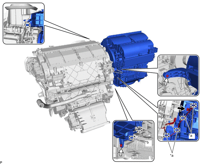
*a Guide (A) *b Guide (B) 
Connector 
Screw -
Disengage 4 guides (A).
-
Remove the 2 screws.
-
Disengage the 2 claws and guide (B) and remove the blower assembly from the air conditioning radiator assembly.
-
-
for RHD:
-
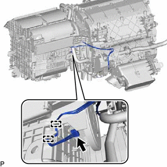
Disconnect the connector.
-
Disengage 2 guides.
-
Remove the 2 screws.
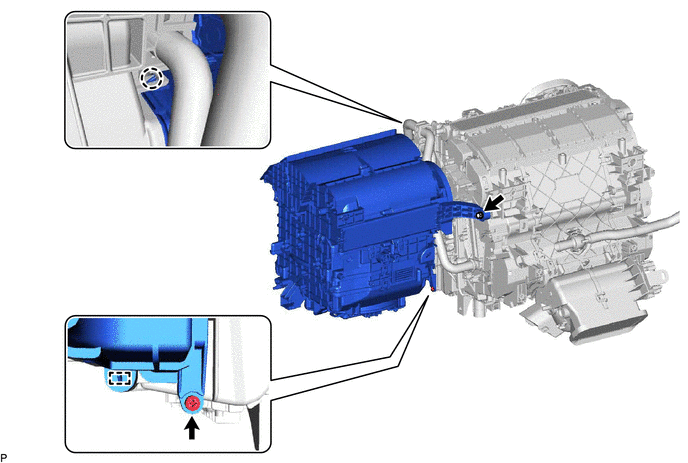
-
Disengage the claw and guide and remove the blower assembly from the air conditioning radiator assembly.
-
-
-
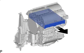
REMOVE AIR FILTER COVER PLATE
-
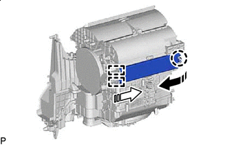

Remove in this Direction (1) 
Remove in this Direction (2) Disengage the claw and 2 guides as indicated by the arrows, in the order shown in the illustration to remove the air filter cover plate.
-
-
REMOVE CLEAN AIR FILTER
-
Remove in this Direction Remove the air filter sub-assembly as shown in the illustration.
-
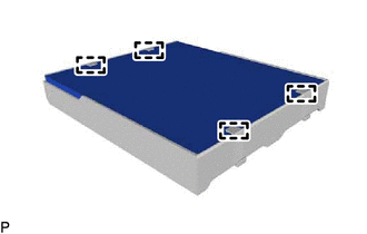
Disengage the 4 guides to remove the clean air filter from the air filter case.
-