NAVIGATION ANTENNA REMOVAL
CAUTION / NOTICE / HINT
The necessary procedures (adjustment, calibration, initialization, or registration) that must be performed after parts are removed and installed, or replaced during navigation antenna assembly removal/installation are shown below.
| Replaced Part or Performed Procedure | Necessary Procedure | Effect/Inoperative Function when Necessary Procedure not Performed | Link |
|---|---|---|---|
| Disconnect cable from negative battery terminal | Memorize steering angle neutral point | LKA/LDA System | |
| Intelligent clearance sonar system*1 | |||
| Pre-crash safety system | |||
| Lighting system (EXT)
|
|||
| Adaptive high beam system | |||
| Drive the vehicle until stop and start control is permitted (approximately 15 to 60 minutes) | Stop and start system | ||
| Memorize steering angle neutral point | Parking assist monitor system (w/ Parallel parking assist function) | ||
| Parking assist monitor system (w/o Parallel parking assist function) | |||
| Panoramic view monitor system | |||
| Initialize back door lock | Power door lock control system | ||
| Reset back door close position | Power back door system | ||
| Removal/installation of the spiral cable with sensor sub-assembly |
|
Parking assist monitor system (w/ Parallel Parking Assist Function) | Click here for Initialization Click here for Calibration |
| Parking assist monitor system (w/o Parallel Parking Assist Function) | Click here for Initialization Click here for Calibration |
||
| Steering angle neutral point (Initialize panoramic view monitor system) | Panoramic view monitor system | Click here for Initialization Click here for Calibration |
|
| Steering angle neutral point (Initialize intelligent clearance sonar system) | Intelligent clearance sonar system |
*1: When performing learning using the GTS.
CAUTION:
Some of these service operations affect the SRS airbag system. Read the precautionary notices concerning the SRS airbag system before servicing.
PROCEDURE
-
REMOVE INSTRUMENT PANEL SAFETY PAD
-
REMOVE DEFROSTER NOZZLE ASSEMBLY
-
REMOVE NAVIGATION ANTENNA ASSEMBLY WITH BRACKET
-
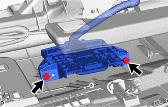
Remove the 2 screws.
-
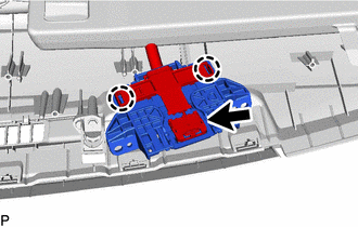
Disengage the 2 claws.
-
Disconnect the connector to remove the navigation antenna assembly with bracket.
-
-
REMOVE NAVIGATION ANTENNA ASSEMBLY
-
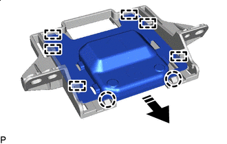

Remove in this Direction Disengage the 2 claws and 6 guides to remove the navigation antenna assembly as shown in the illustration.
-
-
REMOVE NAVIGATION ANTENNA BRACKET