NAVIGATION SYSTEM OPERATION CHECK
-
CHECK NAVIGATION SYSTEM NORMAL CONDITION
-
If the symptom is applicable to any of the following, it is intended behavior, and not a malfunction.
Symptom Answer A longer route than expected is chosen. Depending on the road conditions, the radio receiver assembly may determine that a longer route is quicker. Even when distance priority is high, the shortest route is not shown. Some routes may not be advised due to safety concerns. When the vehicle is put into motion immediately after the engine starts, the navigation system deviates from the correct position. If the vehicle starts before the navigation system activates, the system may not react. When driving on certain types of roads, especially new roads, the vehicle position deviates from the correct position. When the vehicle is driving on new roads not available on the SD card (disc player disc), the system attempts to match it to another nearby road, causing the position mark to deviate. Expected arrival time is earlier than current time, or time different from expected arrival time is displayed. If a destination is set to a point where a different time zone is used, the system displays an expected arrival time corresponding to the time zone of the destination. If a location on the sea is set as the destination, the system may display an expected arrival time corresponding to the time zone setting of the vehicle. Check which communication is not used for displaying traffic information. -
The following symptoms are not malfunctions, but are caused by errors inherent in the GPS, gyro sensor or radio receiver assembly.
-
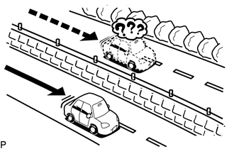
The current position mark may be displayed on a nearby parallel road.
-
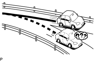
Immediately after a fork in the road, the current vehicle position mark may be displayed on the wrong road.
-
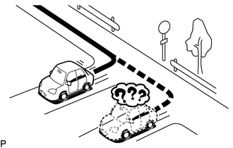
When the vehicle turns right or left at an intersection, the current vehicle position mark may be displayed on a nearby parallel road.
-
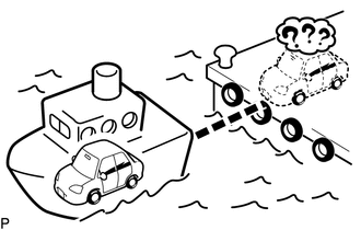
When the vehicle is carried, such as on a ferry, and the vehicle itself is not driving, the current vehicle position mark may be displayed in the position where the vehicle was until a measurement can be performed by the GPS.
-
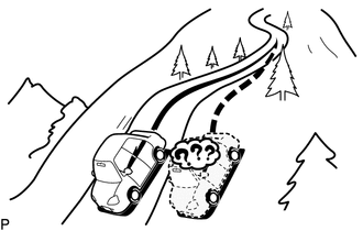
When the vehicle travels on a steep hill, the current vehicle position mark may deviate from the correct position.
-
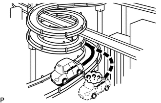
When the vehicle makes a continuous turn (e.g. 360, 720, 1080 degrees), the current vehicle position mark may deviate from the correct position.
-
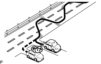
When the vehicle moves erratically, such as constant lane changes, the current vehicle position mark may deviate from the correct position.
-
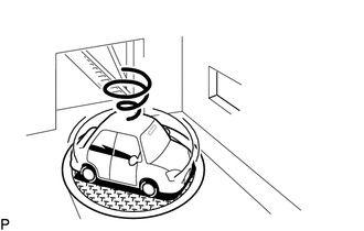
When the engine switch is turned on (ACC) or on (IG) and the vehicle is turned on a turntable before parking, the current vehicle position mark may not indicate the correct direction. The same will occur when the vehicle comes out of the parking garage.
-
When the vehicle travels on a snowy road or a mountain path with tire chains installed or using a spare tire, the current vehicle position mark may deviate from the correct position.
-
When the tires are changed, the current vehicle position mark may deviate from the correct position.
Tech Tips
-
A change in tire diameter may cause a speed sensor error.
-
Performing "tire change" in calibration mode will allow the system to correct the current vehicle position faster.
-
-
-
-
REMOTE TOUCH SELF CHECK
Note
-
Before entering self-diagnostic mode, make sure there are no obstructions which may interfere with operation of the remote touch switch knob, and that the remote touch switch knob is not stuck.
-
Do not touch the remote touch switch knob except when necessary.
Tech Tips
The following checks can be done via self-diagnostic mode:
-
Remote touch DTC check
-
Switch illumination check
-
Remote touch switch knob position recognition check
-
Switch operation check
-
Remote touch switch knob feedback force check
-
Activate Self-diagnostic Mode
-
Turn the light control switch to the off position.
-
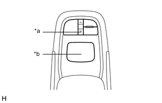
*a Down Switch *b Switch Knob While pressing and holding the down switch and switch knob, turn the engine switch on (ACC) to enter self-diagnostic mode.
-
-
Switch Illumination Check and DTC Check
-
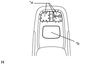
*a Switch Illumination *b Switch Knob Check that the remote touch switch knob automatically moves to the center of the movable area and that the switch illumination blinks.
Tech Tips
During self check mode, all check mode DTCs are stored and the switch illumination blinks at 0.5-second intervals. When the clear conditions for each DTC are met, the DTC is cleared. The switch illumination continues to blink until the self check is complete and all DTCs are cleared.
-
-
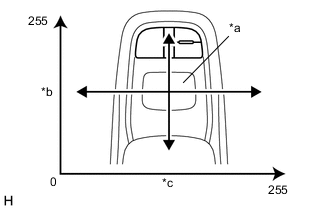
*a Switch Knob *b Longitudinal Axis *c Lateral Axis Remote Touch Switch Knob Position Recognition Check
-
Move the remote touch switch laterally and longitudinally and check that the brightness of the switch illumination changes.
Tech Tips
-
If the brightness of the switch illumination changes according to the position of the remote touch switch knob, the remote touch switch knob position is being correctly recognized.
-
The brightness of the switch illumination changes between 0 and 100% according to the remote touch switch knob coordinates.
-
The remote touch switch coordinates change between 0 and 255 for the lateral axis and between 1 and 255 for the longitudinal axis.
-
When the remote touch switch knob coordinates are 0 for the lateral axis and 1 for the longitudinal axis, the brightness of the switch illumination will be 0% (off). When the coordinates of both the lateral and longitudinal axis are 255, the brightness of the switch illumination will be 100% (full brightness).
-
-
-
Switch Operation Check
-
Check that the switch illumination turns on at 100% brightness when each switch is pressed while the remote touch switch knob is in the lower left position.
Tech Tips
If the switch illumination turns on at 100% brightness when a switch is pressed, the switch being pressed is operating normally.
-
-
Remote Touch Switch Knob Feedback Force Check
-
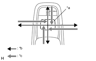
*a Switch Knob *b Movement Direction *c Feedback Force Move the remote touch switch laterally and longitudinally to check that feedback force is generated.
Tech Tips
The motors built into the remote touch generate feedback force according to the direction in which the remote touch switch knob is moved.
-
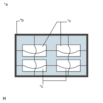
*a Default Feedback Force Image *b Frame Area *c Icon Area Operate the remote touch switch knob to move the pointer displayed on the multi-display assembly*1 or accessory meter assembly*2 screen and check that remote touch generates feedback according to the pointer display position on the multi-display assembly*1 or accessory meter assembly*2.
-
*1: for 8 Inch Display
*2: for 12.3 Inch Display
Tech Tips
-
Refer to Remote Touch Outline for further information on the remote touch switch knob feedback force.
-
If the remote touch generates remote touch switch knob feedback force according to the pointer display position, the remote touch is correctly receiving the feedback force setting signal sent from the radio receiver assembly.
-
If the remote touch cannot receive the feedback force setting signal sent from the radio receiver assembly, use the default feedback force image stored in the remote touch to generate feedback force for the remote touch switch knob.
-
-
-
-
CHECK SD CARD (DISC PLAYER DISC)
Tech Tips
-
Check the SD card (disc player disc) with it installed to the radio receiver assembly.
-
Illustrations may differ from the actual vehicle screen depending on the device settings and options. Therefore, some detailed areas may not be shown exactly the same as on the actual vehicle screen.
-
Enter diagnostic mode.
-

Select "Failure Diagnosis" from the "Service Menu" screen.
-

Select "SD Check" from the "Failure Diagnosis" screen.
-
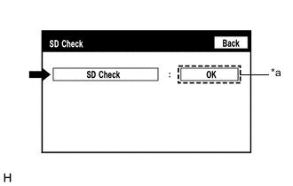
*a Result SD Check
-
Select "SD Check" to start the SD card (disc player disc) check.
-
Check the result displayed when the SD check is complete.
Screen Description Display (Result) Description Checking Check is in progress OK SD card (disc player disc) is normal NG SD card (disc player disc) is malfunctioning Tech Tips
-
After selecting "SD Check", it may take a while until the result is displayed.
-
If the cabin temperature is -20°C (-4°F) or lower, or 65°C (149°F) or higher, the SD card (disc player disc) may not operate normally, and "NG" may be shown on the display. Make sure to perform the inspection with the cabin at an appropriate temperature.
-
If "NG" is displayed even when the cabin temperature is appropriate, replace the SD card (disc player disc) with a new one.
-
-
-
-
CHECK TELEMATICS TRANSCEIVER (w/ Telematics Transceiver for G-BOOK)
Tech Tips
-
Communication between the telematics transceiver and G-BOOK center is checked in the following procedure.
-
Illustrations may differ from the actual vehicle screen depending on the device settings and options. Therefore, some detailed areas may not be shown exactly the same as on the actual vehicle screen.
-
Enter diagnostic mode.
-
Select "Failure Diagnosis" from the "Service Menu" screen.
-
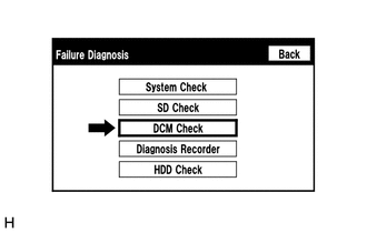
Select "DCM Check" from the "Failure Diagnosis" screen.
-

*a Result Telematics transceiver check
-
Select "DCM Check" to start the telematics transceiver communication condition check.
-
Check the result displayed when the DCM check is complete.
Screen Description Result Description wait While the check is in progress OK Telematics transceiver communication condition is normal NO ANT Telephone antenna is not connected PLL NG PLL is unlocked OFF LINE Service contract is not valid No Service Out of communication service area RESTRICTION Restriction of outgoing signal NO CARRIER RLP link is not established ERROR High priority service is activated TIME OUT Check time out Tech Tips
-
Telematics transceiver check is performed for a maximum of 40 seconds after "DCM Check" is selected.
-
Check the telematics system when "DCM Check" cannot be performed or the check result is not "OK".
-
-
-
-
CHECK HARD DISK DRIVE (HARD DISC) (w/ Sound Library Function)
Tech Tips
-
Check the hard disk drive (hard disc) built into the radio receiver assembly.
-
Illustrations may differ from the actual vehicle screen depending on the device settings and options. Therefore, some detailed areas may not be shown exactly the same as on the actual vehicle screen.
-
Enter diagnostic mode.
-
Select "Failure Diagnosis" from the "Service Menu" screen.
-
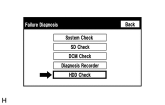
Select "HDD Check" from the "Failure Diagnosis" screen.
-
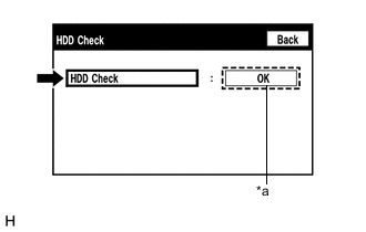
*a Result HDD Check
-
Select "HDD Check" to start the hard disk drive (hard disc) check.
-
Check the result displayed when the hard disk drive (hard disc) check is complete.
Screen Description Display (Result) Description Checking Check is in progress OK Hard disk drive (hard disc) is normal NG Hard disk drive (hard disc) is malfunctioning Tech Tips
-
After selecting "HDD Check", it may take a while until the result is displayed.
-
If the cabin temperature is -20°C (-4°F) or lower, or 65°C (149°F) or higher, the hard disk drive (hard disc) may not operate normally, and "NG" may be shown on the display. Make sure to perform the inspection with the cabin at an appropriate temperature.
-
If "NG" is displayed even when the cabin temperature is appropriate, replace the hard disk drive (hard disc) with a new one.
-
-
-
-
CHECK PANEL & STEERING SWITCH
Tech Tips
-
The radio receiver assembly panel switches and steering switches are checked in the following procedure.
-
Illustrations may differ from the actual vehicle screen depending on the device settings and options. Therefore, some detailed areas may not be shown exactly the same as on the actual vehicle screen.
-
Enter diagnostic mode.
-

Select "Function Check/Setting" from the "Service Menu" screen.
-
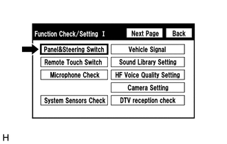
Select "Panel & Steering Switch" from the "Function Check/Setting I" screen.
-
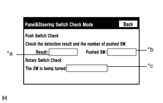
Panel & Steering Switch Check Mode
Screen Description Display Content *a: Switch condition "Pushed" is displayed when any switch is pushed *b: Number of switches pushed
-
Number of switches pushed at once is displayed
-
If 3 switches are pushed at once, "3" or "More than 3" is displayed
-
If 4 or more switches are pushed at once, "More than 3" is displayed
*c: Rotary switch direction Direction of rotary switch is displayed
-
Operate each switch and check that the switch conditions are correctly displayed.
Note
When the "HOME" or "MAP" switch of the remote touch switch is pressed and held for 3 seconds or more, diagnostic mode will be canceled.
-
-
-
CHECK REMOTE TOUCH SWITCH
Tech Tips
-
The remote touch switch knob is checked in the following procedure.
-
Illustrations may differ from the actual vehicle screen depending on the device settings and options. Therefore, some detailed areas may not be shown exactly the same as on the actual vehicle screen.
-
Enter diagnostic mode.
-
Select "Function Check/Setting" from the "Service Menu" screen.
-
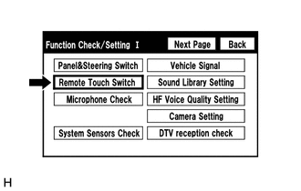
Select "Remote Touch Switch" from the "Function Check/Setting I" screen.
-
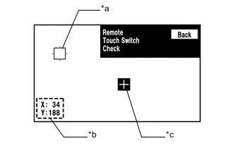
Remote Touch Switch Check
Screen Description Display Content *a: Pointer Displays the location of the pointer. *b: Coordinate
-
Displays the coordinates of the pointer
-
"X" and "Y" indicate the lateral and longitudinal axes
-
Coordinates are displayed by a number between 0 and 255 for lateral axis "X" and a number between 1 and 255 for longitudinal axis "Y" starting from the lower left of the screen
*c: "+" mark Displayed at the location where the pointer was located when the switch knob of the remote touch was pressed.
-
While "Remote Touch Switch Check" is displayed, move the pointer to any blank area of the screen using the remote touch switch knob, and press the switch knob.
Tech Tips
-
The "+" mark is displayed at the pointer position when the switch knob was pressed.
-
Even if the pointer is moved, the "+" mark will remain at the position where the pointer was located when the switch knob was pressed.
-
-
Move the pointer using the remote touch switch knob. When the location of the pointer is changed by moving the switch knob, check that the coordinate value "X" changes between 0 and 255 and coordinate value "Y" changes between 1 and 255.
-
-
-
CHECK MICROPHONE
Tech Tips
-
The microphone and microphone input level are checked in the following procedure.
-
Illustrations may differ from the actual vehicle screen depending on the device settings and options. Therefore, some detailed areas may not be shown exactly the same as on the actual vehicle screen.
-
Enter diagnostic mode.
-
Select "Function Check/Setting" from the "Service Menu" screen.
-
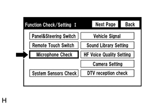
Select "Microphone Check" from the "Function Check/Setting I" screen.
-
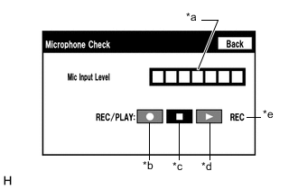
Microphone Check
Screen Description Display Content *a: Microphone input level meter Monitors the microphone input level every 0.1 seconds and displays the results in 8 different levels. *b: Recording switch Starts recording. *c: Stop switch Stops recording and playing. *d: Play switch Plays the recorded voice. *e: Recording indicator Comes on while recording.
-
When speaking into the microphone, check that the microphone input level meter changes according to the input level.
Tech Tips
The microphone is active at all times when this screen is displayed.
-
Push the recording switch and perform voice recording.
Tech Tips
-
Select the recording switch with the blower motor of the air conditioning system stopped. If an outlet of the air conditioning system is facing the microphone, noise may be recorded.
-
While recording or playing, switches other than the stop switch cannot be pushed.
-
When no recording is present, the play switch cannot be pushed.
-
Recording will stop after 5 seconds or when the stop switch is pushed.
-
-
Check that the recording indicator remains on while recording and that the recording can be played normally.
-
-
-
CHECK GPS AND VEHICLE SENSORS
Tech Tips
-
GPS information, vehicle signals and sensor signals are checked in the following procedure.
-
Illustrations may differ from the actual vehicle screen depending on the device settings and options. Therefore, some detailed areas may not be shown exactly the same as on the actual vehicle screen.
-
Enter diagnostic mode.
-
Select "Function Check/Setting" from the "Service Menu" screen.
-
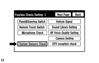
Select "System Sensors Check" from the "Function Check/Setting I" screen.
-
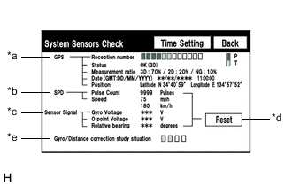
System Sensors Check
*a: GPS Display Content Reception number Displays reception condition of the satellites used to determine vehicle position Blue: P (In use) System is using GPS signal for location. Yellow: T (Receiving) System is tracking GPS signal for location. No color: Not in use System cannot receive GPS signal (searching for GPS signal). Status Displays reception status of the satellites used to determine vehicle position OK (H3D) High accuracy 3-dimensional location method is being used. OK (H2D) High accuracy 2-dimensional location method is being used. OK (3D) 3-dimensional location method is being used. OK (2D) 2-dimensional location method is being used. NG Location data cannot be used. error Reception error has occurred. - Any other state. Measurement ratio Displays the ratio of satellites performing measurements 3D The ratio of satellites performing 3D positioning, Hyper 3D positioning and Hyper 2D positioning is displayed. 2D The ratio of satellites performing 2D positioning is displayed. NG The ratio of satellites not performing measurement is displayed. Date Date/time information obtained from GPS signals is displayed in Greenwich Mean Time (GMT). Position Latitude and longitude information on current position is displayed. *b: SPD Display Content Pulse Count Displays the accumulated number of input pulses beginning when this screen is displayed. Speed Displays the vehicle speed (km/h). *c: Sensor Signal Display Content Note Gyro Voltage Displays the output voltage of the gyro sensor. - 0 point Voltage Displays the zero-point voltage of the gyro sensor. - Relative bearing Displays the output angle of the gyro sensor. The amount of change in bearing angle (degrees) after the system sensor check screen is displayed (clockwise: "+", counterclockwise: "-"). *d: Reset Display Content Reset When this switch is pressed and held for 3 seconds or more, the values of the displayed items of SPD and Sensor Signal will be reset and display "0". *e: Gyro/Distance correction study situation Display Content Gyro/Distance correction study situation Displays the learning status of Gyro/Distance correction.
-
When the "System Sensors Check" screen is displayed, check all of the sensor signals.
Tech Tips
This screen is updated once per second.
-
-
GPS Time Setting
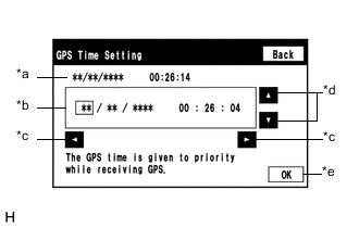
Screen Description Display Content *a: Time display Displays the date and time of the device. *b: Time setting screen Setting is possible only when GPS signals are not being received. *c: Cursor movement switch Moves the cursor on the date and time setting screen to the right and left. *d: Adjustment switch Adjusts values of items selected by the cursor. *e: OK switch Selecting this switch after setting the date and time updates the date and time in the device (only when GPS signals are not received).
-
When GPS signals are not being received, the date and time in the device can be adjusted.
Tech Tips
-
The telematics system cannot be used in areas where GPS signals are not being received. As a result, when using the telematics system in areas such as indoors, set the GPS time from the GPS time setting screen. (w/ Telematics System)
-
Time setting is possible only when GPS signals are not being received. When the navigation system is receiving GPS signals, priority is given to displaying the time and date received via GPS.
-
-
-
-
CHECK VEHICLE SIGNAL
Tech Tips
-
Vehicle signals received by the radio receiver assembly are checked in the following procedure.
-
Illustrations may differ from the actual vehicle screen depending on the device settings and options. Therefore, some detailed areas may not be shown exactly the same as on the actual vehicle screen.
-
Enter diagnostic mode.
-
Select "Function Check/Setting" from the "Service Menu" screen.
-
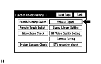
Select "Vehicle Signal" from the "Function Check/Setting I" screen.
-
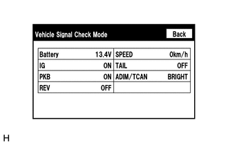
Vehicle Signal Check Mode
Screen Description Display Content Battery Battery voltage is displayed. IG Engine switch ON/OFF state is displayed. PKB Parking brake ON/OFF state is displayed. REV Reverse signal ON/OFF state is displayed. SPEED Vehicle speed is displayed in km/h. TAIL Tail signal (light control switch) ON/OFF state is displayed. ADIM/TCAN Brightness state DIM (with)/BRIGHT (without) is displayed. Tech Tips
-
Only items sending vehicle signals will be displayed.
-
This screen displays vehicle signals input to the radio receiver assembly.
-
This screen is updated once per second.
-
When the "Vehicle Signal Check Mode" screen is displayed, check all of the vehicle signal conditions.
-
-
-
CHECK SOUND LIBRARY SETTING (w/ Sound Library Function)
Tech Tips
-
It is possible to check the sound library information and turn the sound library function on and off.
-
Illustrations may differ from the actual vehicle screen depending on the device settings and options. Therefore, some detailed areas may not be shown exactly the same as on the actual vehicle screen.
-
Enter diagnostic mode.
-
Select "Function Check/Setting" from the "Service Menu" screen.
-
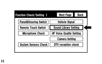
Select "Sound Library Setting" from the "Function Check/Setting I" screen.
-
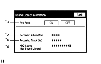
Sound Library Information
Screen Description Display Content *a: Recording function setting for hard disk drive (hard disc) Recording to hard disk drive (hard disc) permitted (ON)/not permitted (OFF) *b: Number of albums Number of albums recorded on hard disk drive (hard disc) *c: Number of tracks Number of tracks recorded on hard disk drive (hard disc) *d: Free space in hard disk drive (hard disc) Free space on hard disk drive (hard disc) partition for sound library
-
-
CHECK HANDS-FREE VOICE QUALITY AND VOLUME SETTING
Note
-
These settings are adjusted separately for each registered cellular phone.
-
If a cellular phone has not been registered, the settings cannot be adjusted.
Tech Tips
-
The hands-free volume of a "Bluetooth" compatible phone can be adjusted using the following procedure.
-
Illustrations may differ from the actual vehicle screen depending on the device settings and options. Therefore, some detailed areas may not be shown exactly the same as on the actual vehicle screen.
-
Enter diagnostic mode.
-
Select "Function Check/Setting" from the "Service Menu" screen.
-
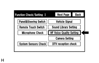
Select "HF Voice Quality Setting" from the "Function Check/Setting I" screen.
-
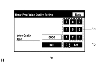
*a Numeric Keypad *b Setting Button *c Reset Button Hands-Free Voice Quality Setting (Voice Quality Type adjustment)
-
If necessary, refer to the table below to adjust the voice quality type with the numeric keypad.
-
When adjusting the settings, use the number pad on the screen to input the voice quality type according to the table.
Settings Parameter Target Phenomenon Voice Quality Type Positive Effect of Changing Voice Quality Negative Effect of Changing Voice Quality A
(Noise)
The other party hears background noise when listening to your voice. 1000 The amount of background noise the other party hears when listening to your voice is reduced. The volume of voice the other party hears when listening to your voice may temporarily drop. B
(Noise)
The other party hears a lot of background noise when listening to your voice. 2000 The amount of background noise the other party hears when listening to your voice is sharply reduced. The volume of voice the other party hears when listening to your voice may temporarily drop. C
(Echo)
The other party hears weak echoes. 0100 The amount of echo is reduced (low level). Sound quality of the other party deteriorates (low level). D
(Echo)
The other party hears strong echoes. 0200 The amount of echo is reduced (high level). Sound quality of the other party deteriorates (high level). Settings (When Multiple Phenomenon Occurred) Parameter Target Phenomenon Voice Quality Type Positive Effect of Changing Voice Quality Negative Effect of Changing Voice Quality A+C The other party hears background noise and weak echoes when listening to your voice. 1100
-
The amount of background noise the other party hears when listening to your voice is reduced.
-
The amount of echo is reduced (low level).
-
The volume of voice may drop temporarily.
-
Sound quality of the other party deteriorates (low level).
A+D The other party hears background noise and strong echoes when listening to your voice. 1200
-
The amount of background noise the other party hears when listening to your voice is reduced.
-
The amount of echo is reduced (high level).
-
The volume of voice may drop temporarily.
-
Sound quality of the other party deteriorates (high level).
B+C The other party hears a lot of background noise and weak echoes when listening to your voice. 2100
-
The amount of background noise the other party hears when listening to your voice is sharply reduced.
-
The amount of echo is reduced (low level).
-
The volume of voice may drop temporarily.
-
Sound quality of the other party deteriorates (low level).
B+D The other party hears a lot of background noise and strong echoes when listening to your voice. 2200
-
The amount of background noise the other party hears when listening to your voice is sharply reduced.
-
The amount of echo is reduced (high level).
-
The volume of voice may drop temporarily.
-
Sound quality of the other party deteriorates (high level).
Tech Tips
-
The default value is "0000".
-
Settings will be applied when the setting button is selected.
-
If voice quality type values that are not in the table are input, the setting will not be applied and a positive effect may not be gained.
-
If the quality of phone calls decreases due to the changed settings, return the settings to "0000" by selecting "INIT".
-
-
-
-
CHECK DIGITAL TV RECEPTION (w/ Digital TV Function)
Tech Tips
-
The reception condition of Digital TV (DTV) can be checked.
-
Illustrations may differ from the actual vehicle screen depending on the device settings and options. Therefore, some detailed areas may not be shown exactly the same as on the actual vehicle screen.
-
Enter diagnostic mode.
-

Select "Function Check/Setting" from the "Service Menu" screen.
-
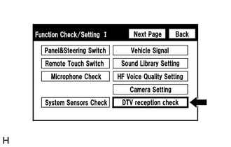
Select "DTV reception check" from the "Function Check/Setting I" screen.
-
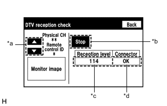
DTV reception check
Screen Description Display Content *a: Up or down switch Enables the channel to be changed to the one to be checked. *b: Recheck/Stop switch
-
Recheck: Starts checking
-
Stop: Stops checking
*c: Digital TV tuner reception level check result
-
111 or more: Font color is black (good reception)
-
110 or less: Font color is red (poor reception)
-
-: Not equipped with digital TV antenna
Displays digital TV antenna reception level as follows:
*d: Antenna connection check
-
OK: Connected properly
-
NG: Not connected properly
-
-: Not equipped with digital TV antenna
Displays digital TV antenna connection status as follows:
Tech Tips
-
As digital TV is a terrestrial broadcast, the digital TV antenna cannot receive the signal in places where the signal may not reach the vehicle, such as mountains or tunnels.
-
Even in areas where digital TV broadcasts for households can be received, the in-vehicle digital TV may not be able to receive the broadcast.
-
Select "Recheck" to start the DTV reception check.
-
Check the result displayed when the DTV reception check is complete.
Tech Tips
-
Do not depend solely on the reception level as a reference value as it may vary depending on the signal conditions such as wave interference.
-
If the result changes after turning the vehicle around, it is not due to a malfunction, but is caused by a local weak electric field.
-
If the reception level is abnormal, the antenna system or radio receiver assembly is malfunctioning.
-
-
-
-
CHECK DAB RECEPTION (w/ DAB Function)
Tech Tips
-
The reception condition of Digital Audio Broadcast (DAB) can be checked.
-
Illustrations may differ from the actual vehicle screen depending on the device settings and options. Therefore, some detailed areas may not be shown exactly the same as on the actual vehicle screen.
-
Enter diagnostic mode.
-
Select "Function Check/Setting" from the "Service Menu" screen.
-
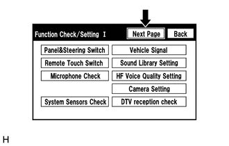
Select "Next Page" from the "Function Check/Setting I" screen.
-
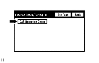
Select "DAB Reception Check" from the "Function Check/Setting II" screen.
-
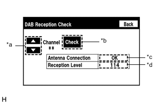
DAB Reception Check
Screen Description Display Content *a: Up or down switch Enables the channel to be changed to the one to be checked. *b: Check/STOP switch
-
Check: Starts checking
-
STOP: Stops checking
*c: Antenna connection check
-
OK: Connected properly
-
NG: Not connected properly
-
-: Not equipped with DAB antenna.
Displays DAB antenna connection status as follows:
*d: DAB Tuner Reception Level Check Result Description
-
111 or more: Font color is black (good reception)
-
110 or less: Font color is red (poor reception)
-
-: Not equipped with DAB antenna.
Displays DAB antenna reception level as follows:
-
Select "Check" to start the DAB reception check.
-
Check the results displayed when the DAB reception check is completed.
Tech Tips
If the reception level is abnormal, the antenna system or radio receiver assembly is malfunctioning.
-
-
-
CLEAR PASSWORD OF EXPORT/IMPORT MEMORY POINT FUNCTION
Tech Tips
-
This function allows the initialization of a password which was set on the radio receiver assembly when exporting/importing memory points.
-
Illustrations may differ from the actual vehicle screen depending on the device settings and options. Therefore, some detailed areas may not be shown exactly the same as on the actual vehicle screen.
-
Enter diagnostic mode.
-
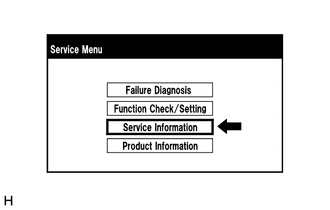
Select "Service Information" from the "Service Menu" screen.
-
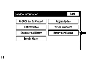
Select "Memory point backup" from the "Service Information" screen.
-
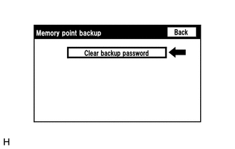
Clear backup password
Tech Tips
Depending on the manufacturer, some component names and versions will be displayed differently.
-
Select "Clear backup password" from the "Memory point backup" screen.
-
-
-
CHECK SPEAKER
Tech Tips
-
This function is used when checking the speaker wiring and whether the speakers are functioning properly.
-
Illustrations may differ from the actual vehicle screen depending on the device settings and options. Therefore, some detailed areas may not be shown exactly the same as on the actual vehicle screen.
-
Turn radio receiver assembly on and play any audio source.
Tech Tips
This audio source will be used for the speaker check.
-
Enter diagnostic mode.
-
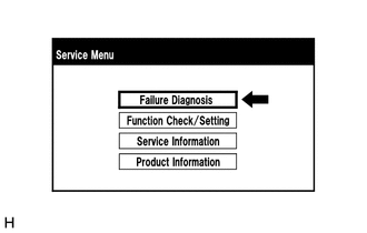
Select "Failure Diagnosis" from the "Service Menu" screen.
-
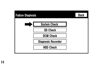
Select "System Check" from the "Failure Diagnosis" screen.
-
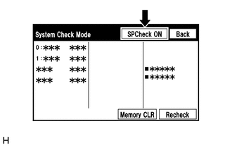
Select "SP Check ON" from the "System Check Mode" screen.
-
Check the speaker wiring and check that the speakers are functioning properly.
Tech Tips
-
Check that each speaker outputs sound from the selected audio source properly.
-
"SP Check OFF" is displayed during the speaker check.
-
Sound can be heard from the speakers around the vehicle in order beginning from a speaker on the front side.
-
More than one speaker may sound simultaneously depending on the speaker wiring.
-
-
Sound stops when any of the following conditions are met:
-
"SP Check OFF" is selected.
-
The engine switch is turned off.
-
Diagnostic mode is turned off.
-
The screen is changed to another screen.
-
Audio mode is turned off.
-
-
-
CHECK SOFTWARE ERROR HISTORY
Tech Tips
This function is used to check the cause when the radio receiver assembly screen is blacked out.
-
Check software error history.
-
Connect the GTS to the DLC3.
-
Turn the engine switch on (IG).
-
Turn the GTS on.
-
Enter the following menus: Body Electrical / Navigation System / Utility / Software Error History.
Body Electrical > Navigation System > UtilityTester Display Software Error History -
When an item is stored for Software Error History, record it before performing repairs.
Software Error History Screen Description Error Description Trigger Detail Software Reset Navi Microcomputer Hexadecimal Number Audio Microcomputer CAN Microcomputer No Video Signal Front Monitor Rear Monitor MOST Cold Restart Always Tech Tips
-
Software Error History can store up to 5 history data items. If a new software error occurs when 5 data items have already been stored, the oldest data is cleared and the new data is stored.
-
If an error that is unsupported by the GTS occurs, "-" is displayed for the display items.
-
-
-
Clear software error history.
-
When DTCs are cleared using any of the following operations, Software Error History will be cleared as well.
-
Cleared using the GTS.
-
Cleared using the system check mode screen.
-
Cleared using the unit check mode screen.
-
-
-
-
CHECK OPTICAL DISC ERROR HISTORY
Tech Tips
This function is used to check the cause when an optical disc error occurs.
-
Check optical disc error history.
-
Connect the GTS to the DLC3.
-
Turn the engine switch on (IG).
-
Turn the GTS on.
-
Enter the following menus: Body Electrical / Navigation System / Utility / Optical Disc Error History.
Body Electrical > Navigation System > UtilityTester Display Optical Disc Error History -
When an item is stored for Optical Disc Error History, record it before proceeding with troubleshooting.
Optical Disc Error History Screen Description Display Content Error Type Displays the type of error. Device Displays the malfunctioning device. Date Displays the date and time that the malfunction occurred. "Error Type" Screen Description Error Type Detection Condition Action Read Error When a disc read error occurs. Proceed to next suspected area shown in Problem Symptoms Table
Disc damaged/up side down/dirty When it is determined that any of the following is the cause of the disc read error:
-
The disc cannot be read.
-
The disc cannot be read because of dirt or scratches.
-
The disc cannot be read because it is inserted upside down.
Cannot determine disc type An unsuitable disc is inserted. DSP error When an error occurs while decoding MP3/WMA/AAC files. Some files are corrupt
-
When MP3/WMA/AAC files cannot be played back because they are unsupported.
-
Even though the file extensions are appropriate for MP3, WMA or AAC files, cannot be played back because the header information cannot be read.
Some files cannot be found
-
When a disc without music data is played back.
-
When there are no playable MP3/WMA/AAC files.
Copy protection violation When a file with copyright protection that cannot be played back is played back. "Device" Screen Description Device Component DVD-P Radio receiver assembly CD-P Not available R-Seat DVD-P Not available Tech Tips
-
Optical Disc Error History can store up to 7 history data items. If a new optical disc error occurs when 7 data items have already been stored, the oldest data is cleared and the new data is stored.
-
If an error that is unsupported by the GTS occurs, "-" or blank is displayed for the display items.
-
-
-
Clear optical disc error history.
-
When DTCs are cleared using any of the following operations, Optical Disc Error History will be cleared as well.
-
Cleared using the GTS.
-
Cleared using the system check mode screen.
-
Cleared using the unit check mode screen.
-
-
-
-
Tech Tips
-
This function is used to detect disconnection of the video devices.
-
In order to inspect the RSE, a disc should be inserted into the radio receiver assembly.
CHECK VIDEO DEVICE CONNECTION CHECK
-
Check Video Device Connection Check.
-
Connect the GTS to the DLC3.
-
Turn the engine switch on (IG).
-
Turn the GTS on.
-
Enter the following menus: Body Electrical / Navigation System / Utility / Video Device Connection Check.
Body Electrical > Navigation System > UtilityTester Display Video Device Connection Check -
When an item is stored for Video Device Connection Check, record it before proceeding with troubleshooting.
Tech Tips
-
DTCs are stored when errors are detected.
-
Depending on the vehicle, some of the items will not be displayed on the "Error Detected Image Line (Type)" screen.
Video Device Connection Check Screen Description Error Detected Image Line (Type) Areas to be Checked H/U - > Separate Display (GVIF) Digital video signal between the radio receiver assembly and multi-display assembly*1 or accessory meter assembly*2 H/U - > Full RSE (GVIF) Digital video signal between the radio receiver assembly and multi-display controller sub-assembly*3 RSE - > Seat Back Display RH (GVIF) Digital video signal between the multi-display controller sub-assembly and television display assembly RH*3 RSE - > Seat Back Display LH (GVIF) Digital video signal between the multi-display controller sub-assembly and television display assembly LH*3 Rear Camera - > H/U (NTSC) NTSC video signal between the radio receiver assembly and rear television camera assembly IPA/BGM/PVM ECU - > Separate Display (GVIF) Digital video signal between the parking assist ECU*4 and multi-display assembly*1 or accessory meter assembly*2 IPA/BGM/PVM ECU - > H/U (NTSC) NTSC video signal between the parking assist ECU and radio receiver assembly*4 IPA/BGM/PVM ECU - > H/U (GVIF) Not available
-
*1: for 8 Inch Display
*2: for 12.3 Inch Display
*3: w/ Rear Seat Entertainment System
*4: w/ Panoramic View Monitor System
-
-
-
Clear video device connection check.
-
When DTCs are cleared using any of the following operations, Video Device Connection Check will be cleared as well.
-
Cleared using the GTS.
-
Cleared using the system check mode screen.
-
Cleared using the unit check mode screen.
-
-
-
-
MAP INFORMATION
Tech Tips
This function is used to check the map version of the navigation system.
-
Check map information.
-
Connect the GTS to the DLC3.
-
Turn the engine switch on (IG).
-
Turn the GTS on.
-
Enter the following menus: Body Electrical / Navigation System / Utility / Map Information.
Body Electrical > Navigation System > UtilityTester Display Map Information -
Check the map version of the navigation system.
-
-
-
CHECK "Wi-Fi" CONNECTION HISTORY (w/ "Wi-Fi" Function)
Tech Tips
This function is used to check the connection history when the connection between the radio receiver assembly and a "Wi-Fi" device is unstable.
-
Check "Wi-Fi" Connection History.
-
Connect the GTS to the DLC3.
-
Turn the engine switch on (IG).
-
Turn the GTS on.
-
Enter the following menus: Body Electrical / Navigation System / Utility / "Wi-Fi" Connection History.
Body Electrical > Navigation System > UtilityTester Display Wi-Fi Connection History -
When a value for an item is displayed in "Wi-Fi" Connection History, record it before proceeding with troubleshooting.
"Wi-Fi" Connection History Screen Description Item Content Occurrence Date/Time Year is displayed in 4 digits and month, date, hour, minute and second are displayed in 2 digits Result Connect/Disconnect Success Timeout Communication Error Authentication Failure Disconnection Failure Other Failure Contents No Error AP Connection Error AP Connection Error (WPS) DHCP Connection Error DNS Connection Error HTTP Connection Error Other Error Destination MAC Address Displayed in lower case hexadecimal format with "-" inserted every two characters. Destination SSID Data is displayed as ASCII code WLAN Standard 802.11 b 802.11 g 802.11 n Undetectability Received Signal Strength -127 dBm to +127 dBm Data Rate 1.0 Mbps 2.0 Mbps 5.5 Mbps 6.0 Mbps 6.5 Mbps 9.0 Mbps 11.0 Mbps 12.0 Mbps 13.0 Mbps 18.0 Mbps 19.5 Mbps 24.0 Mbps 26.0 Mbps 36.0 Mbps 39.0 Mbps 48.0 Mbps 52.0 Mbps 54.0 Mbps 58.5 Mbps 65.0 Mbps Undetectability Packet Error Rate Displayed in decimal format with "%" Tech Tips
If there is nothing to display in the "Content" column, "-" or "No Information" is displayed.
-
-
Clear "Wi-Fi" connection history.
-
When DTCs are cleared using any of the following operations, "Wi-Fi" Connection History will be cleared as well.
-
Cleared using the GTS.
-
Cleared using the system check mode screen.
-
Cleared using the unit check mode screen.
-
-
-
-
MAP DATA UPDATE ERROR CODE (w/ Sound Library Function)
-
When updating the map data, the following error codes will be output if the update does not complete successfully. Perform troubleshooting according to the "Action to be Taken" column of each error code.
Type of Update: 03 (Update to Restore Data Using USB Device) Error Code Error Occurrence Condition Cause of Error Navigation System Status Action to be Taken from 01 to 2F:
System malfunction
01: Updating program (downloading)
-
Data corrupted during download
-
Data cannot be read due to problem with USB device.
Available
-
Using another USB device, obtain another update package and update the map data.
-
If the same error code is output again, replace the SD card (disc player disc) and update the map data.
-
If the same error code is output again, replace the radio receiver assembly.
from 30 to 4F:
Program update error
-
Temporary failure due to external factors such as vibration or excessive temperature
-
Hardware malfunction
Available
-
Using another USB device, obtain another update package and update the map data.
-
If the same error code is output again, replace the SD card (disc player disc) and update the map data.
-
If the same error code is output again, replace the radio receiver assembly.
from 50 to FF:
Internal error
Hardware failure Available
-
Using another USB device, obtain another update package and update the map data.
-
If the same error code is output again, replace the SD card (disc player disc) and update the map data.
-
If the same error code is output again, replace the radio receiver assembly.
from 01 to 2F:
System malfunction
02: Updating program (installing)
-
Temporary failure due to external factors such as vibration or excessive temperature
-
Hardware malfunction
Available
-
Using another USB device, obtain another update package and update the map data.
-
If the same error code is output again, replace the SD card (disc player disc) and update the map data.
-
If the same error code is output again, replace the radio receiver assembly.
from 30 to 4F:
Program update error
-
Temporary failure due to external factors such as vibration or excessive temperature
-
Hardware malfunction
Available
-
Using another USB device, obtain another update package and update the map data.
-
If the same error code is output again, replace the SD card (disc player disc) and update the map data.
-
If the same error code is output again, replace the radio receiver assembly.
from 50 to FF:
Internal error
Hardware failure Available
-
Using another USB device, obtain another update package and update the map data.
-
If the same error code is output again, replace the SD card (disc player disc) and update the map data.
-
If the same error code is output again, replace the radio receiver assembly.
from 01 to 2F:
System malfunction
03: Copying map data
-
Temporary failure due to external factors such as vibration or excessive temperature
-
Hardware malfunction
Available or cannot display map data
-
Using another USB device, obtain another update package and update the map data.
-
If the same error code is output again, replace the SD card (disc player disc) and update the map data.
-
If the same error code is output again, replace the radio receiver assembly.
from 30 to 4F:
File cannot be read or written
-
SD card (disc player disc) is not inserted or connected properly
-
Temporary failure due to external factors such as vibration or excessive temperature
-
Hardware malfunction
Available or cannot display map data
-
Using another USB device, obtain another update package and update the map data.
-
Turn the engine switch off.
-
Turn the engine switch on (ACC).
-
Properly insert the SD card (disc player disc) and update the map data.
-
If the same error code is output again, replace the SD card (disc player disc) and update the map data.
-
If the same error code is output again, replace the radio receiver assembly.
from 50 to 6F:
Media update error
-
Data corrupted during download
-
Data cannot be read due to problem with USB device.
Available or cannot display map data
-
Using another USB device, obtain another update package and update the map data.
-
If the same error code is output again, replace the SD card (disc player disc) and update the map data.
-
If the same error code is output again, replace the radio receiver assembly.
from 70 to 8F:
File operation error
-
SD card (disc player disc) is not inserted or connected properly
-
Temporary failure due to external factors such as vibration or excessive temperature
-
Hardware malfunction
Available or cannot display map data
-
Using another USB device, obtain another update package and update the map data.
-
Turn the engine switch off.
-
Turn the engine switch on (ACC).
-
Properly insert the SD card (disc player disc) and update the map data.
-
If the same error code is output again, replace the SD card (disc player disc) and update the map data.
-
If the same error code is output again, replace the radio receiver assembly.
from 90 to FF:
Internal error
Hardware failure Available or cannot display map data
-
Using another USB device, obtain another update package and update the map data.
-
If the same error code is output again, replace the SD card (disc player disc) and update the map data.
-
If the same error code is output again, replace the radio receiver assembly.
-
-
-
ENFORM RESET PROCEDURE (w/ Enform Function)
-
Duplicate the problem symptom.
-
Check for DTCs and repair the systems for which any DTCs are output.
-
Check cellular phone compatibility.
-
Check if the cellular phone/vehicle is compatible (Refer to http://www.lexus.com.au/).
-
If the cellular phone is not compatible, recommend to the customer a compatible cellular phone.
-
-
Delete all paired devices from the cellular phone.
-
The procedure varies based on phone model. Contact the service provider or cellular phone manufacturer if assistance is required.
-
-
Remove the Enform app from the phone.
Note
Only perform this step if the customer is present and approves.
-
The procedure varies based on phone model. Contact the service provider or cellular phone manufacturer if assistance is required.
-
-
Reset the phone.
Note
Only perform this step if the customer is present and approves.
-
Turn off the phone and remove the battery for 15 seconds. For instructions on how to reset cellular devices, refer to the appropriate manufacturer's website.
-
-
Reinstall the Enform app on the phone. (If removed.)
-
The procedure varies based on phone model. Contact the service provider or cellular phone manufacturer if assistance is required.
-
-
Delete all personal data from the head unit.
-
Delete all personal data from the head unit.
Note
Only perform this step if the customer is present and approves.
Tech Tips
Re-installation of applications must be completed before applications will appear on the head unit.
-
-
Disconnect the cable from the negative (-) battery terminal.
Note
After turning the engine switch off, waiting time may be required before disconnecting the cable from the negative (-) battery terminal. Therefore, make sure to read the disconnecting the cable from the negative (-) battery terminal notices before proceeding with work.
-
Record all radio station presets.
-
Disconnect the cable from the negative (-) battery terminal and leave it disconnected for 2 minutes.
-
-
Check if the problem symptom disappears.
-