RADIO ANTENNA CORD(w/ Rear No. 2 Seat) INSTALLATION
PROCEDURE
-
INSTALL NO. 4 ANTENNA CORD SUB-ASSEMBLY
-
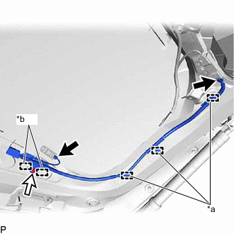
*a Clamp *b Guide Engage the 3 clamps and 2 guides.
-
Connect each connector.
-
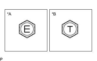
*A for Type A *B for Type B Install the No. 4 antenna cord sub-assembly with the bolt.
- Torque:
- for Type A
- 8.35 N*m { 85 kgf*cm, 74 in.*lbf }
- for Type B
- 10 N*m { 102 kgf*cm, 7 ft.*lbf }
Note
There are two types of bolts and the tightening torque depends on the type of bolt used as shown in the illustration. Therefore, confirm the tightening torque before installing the bolt.
-
-
INSTALL NO. 3 ANTENNA CORD SUB-ASSEMBLY
-
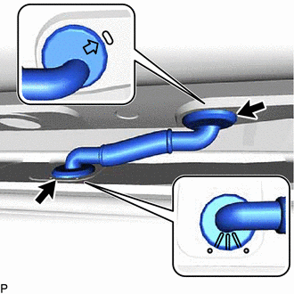
Engage the 2 grommets as shown in the illustration.
-
Connect the washer hose.
-
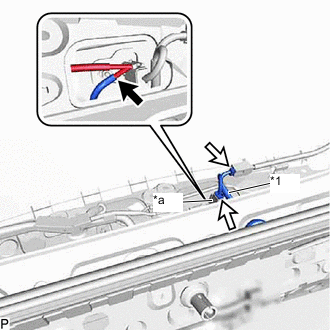
*1 No. 3 Antenna Cord Sub-assembly *a Connector Connect the 2 connectors and washer hose to install the No. 3 antenna cord sub-assembly.
Note
Route the No. 3 antenna cord sub-assembly around the right side of the connector as shown in the illustration.
-
-
INSTALL BACK DOOR TRIM PANEL ASSEMBLY
-
INSTALL NO. 1 LUGGAGE COMPARTMENT LIGHT ASSEMBLY
-
INSTALL DOOR PULL HANDLE
-
INSTALL BACK DOOR TRIM BASE
-
INSTALL BACK DOOR LOCK COVER
-
INSTALL BACK DOOR TRIM COVER LH
-
INSTALL BACK DOOR TRIM COVER RH
Tech Tips
Use the same procedure as for the LH side.
-
INSTALL BACK WINDOW UPPER PANEL TRIM
-
INSTALL NO. 5 ANTENNA CORD SUB-ASSEMBLY (for Type A)
-
Engage each clamp.
-
Connect each connector to install the No. 5 antenna cord sub-assembly.
-
-
INSTALL NO. 6 ANTENNA CORD SUB-ASSEMBLY (for Type B)
-
Engage each clamp.
-
Connect each connector to install the No. 6 antenna cord sub-assembly.
-
-
INSTALL NO. 2 ANTENNA CORD SUB-ASSEMBLY
Tech Tips
Butyl tape and adhesive tape are not available as supply parts. If these pieces of tape still have enough adhesion to secure the No. 2 antenna cord sub-assembly to the roof headlining assembly, reuse them. If the adhesive tape and/or the butyl tape is no longer sticky, apply new tape following the procedure below.
-
w/o Television Antenna:
-
Apply new butyl tape.
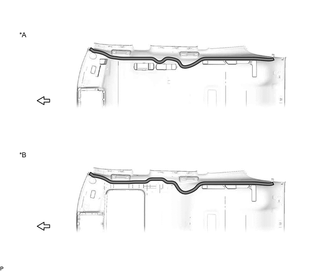
*A for Standard Roof *B for Sliding Roof 
Butyl tape 
Front
-
Remove the old butyl tape from the roof headlining assembly.
-
Prepare an appropriate amount of new butyl tape.
Tech Tips
Be careful not to touch the adhesive surface.
-
Apply the butyl tape to the roof headlining assembly while aligning the tape with the markings on the roof headlining assembly.
-
Peel off the release paper from the butyl tape.
-
-
Align the marking tape on the No. 2 antenna cord sub-assembly with the markings on the roof headlining assembly and install the No. 2 antenna cord sub-assembly to the butyl tape.
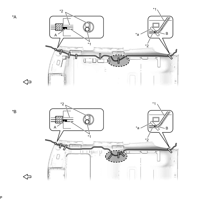
*A for Standard Roof *B for Sliding Roof *1 No. 2 Antenna Cord Sub-assembly *2 Washer Hose Assembly *a Marking - - 
Adhesive Tape 
Marking Tape 
Adjustment Area Front -
Put the pieces of adhesive tape back to the positions shown in the illustration to secure the No. 2 antenna cord sub-assembly and washer hose assembly to the roof headlining assembly.
Tech Tips
-
If the tape is no longer sticky, use other tape, such as packing tape, that has enough adhesion to secure the antenna cord to the roof headlining assembly.
-
Align the marking tape (A) on the No. 2 antenna cord sub-assembly with the base of the protrusion on the front right side of the roof headlining assembly and wrap tape around the No. 2 antenna cord sub-assembly, washer hose assembly and roof headlining assembly to secure them.
-
Align the marking tape (B) on the No. 2 antenna cord sub-assembly with the marking on the rear of the roof headlining assembly and secure the No. 2 antenna cord sub-assembly and washer hose assembly with the No. 2 antenna cord sub-assembly on the outer side of the washer hose assembly.
-
Align the marking tape (C) on the No. 2 antenna cord sub-assembly with the marking on the front of the roof headlining assembly and secure the No. 2 antenna cord sub-assembly. (w/ Television Antenna)
-
Secure the extra length of the No. 2 antenna cord sub-assembly in the adjustment area shown in the illustration.
-
-
-
w/ Television Antenna:
-
Apply new butyl tape.
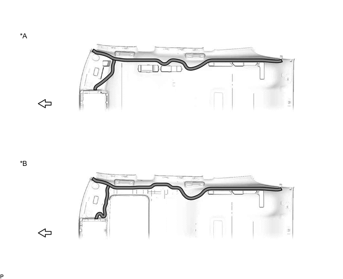
*A for Standard Roof *B for Sliding Roof Butyl tape Front
-
Remove the old butyl tape from the roof headlining assembly.
-
Prepare an appropriate amount of new butyl tape.
Tech Tips
Be careful not to touch the adhesive surface.
-
Apply the butyl tape to the roof headlining assembly while aligning the tape with the markings on the roof headlining assembly.
-
Peel off the release paper from the butyl tape.
-
-
Align the marking tape on the No. 2 antenna cord sub-assembly with the markings on the roof headlining assembly and install the No. 2 antenna cord sub-assembly to the butyl tape.
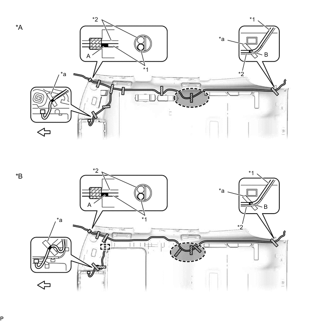
*A for Standard Roof *B for Sliding Roof *1 No. 2 Antenna Cord Sub-assembly *2 Washer Hose Assembly *a Marking - - Adhesive Tape Marking Tape Adjustment Area Front -
for Sliding Roof:
-
Engage the clamp.
-
-
Put the pieces of adhesive tape back to the positions shown in the illustration to secure the No. 2 antenna cord sub-assembly and washer hose assembly to the roof headlining assembly.
Tech Tips
-
If the tape is no longer sticky, use other tape, such as packing tape, that has enough adhesion to secure the antenna cord to the roof headlining assembly.
-
Align the marking tape (A) on the No. 2 antenna cord sub-assembly with the base of the protrusion on the front right side of the roof headlining assembly and wrap tape around the No. 2 antenna cord sub-assembly, washer hose assembly and roof headlining assembly to secure them.
-
Align the marking tape (B) on the No. 2 antenna cord sub-assembly with the marking on the rear of the roof headlining assembly and secure the No. 2 antenna cord sub-assembly and washer hose assembly with the No. 2 antenna cord sub-assembly on the outer side of the washer hose assembly.
-
Align the marking tape (C) on the No. 2 antenna cord sub-assembly with the marking on the front of the roof headlining assembly and secure the No. 2 antenna cord sub-assembly. (w/ Television Antenna)
-
Secure the extra length of the No. 2 antenna cord sub-assembly in the adjustment area shown in the illustration.
-
-
-
-
INSTALL ROOF HEADLINING ASSEMBLY
-
INSTALL ANTENNA CORD SUB-ASSEMBLY
-
Engage each clamp to install the antenna cord sub-assembly.
-
w/ Navigation Antenna:
-
Connect the connector.
-
Engage the 2 claws.
-
-
-
INSTALL ION GENERATOR SUB-ASSEMBLY (for RHD)
w/ Ion Generator:
-
INSTALL NO. 2 SIDE DEFROSTER NOZZLE DUCT
-
INSTALL NO. 1 SIDE DEFROSTER NOZZLE DUCT (for RHD)
-
INSTALL NO. 4 HEATER TO REGISTER DUCT
-
INSTALL NO. 1 HEATER TO REGISTER DUCT (for RHD)
-
INSTALL HEADUP DISPLAY (METER MIRROR SUB-ASSEMBLY) (for RHD)
w/ Headup Display:
-
INSTALL INSTRUMENT PANEL SAFETY PAD SUB-ASSEMBLY