RADIO ANTENNA CORD(w/ Rear No. 2 Seat) REMOVAL
CAUTION / NOTICE / HINT
The necessary procedures (adjustment, calibration, initialization, or registration) that must be performed after parts are removed and installed, or replaced during antenna cord sub-assembly removal/installation are shown below.
| Replaced Part or Performed Procedure | Necessary Procedure | Effect/Inoperative Function when Necessary Procedure not Performed | Link |
|---|---|---|---|
| Disconnect cable from negative battery terminal | Memorize steering angle neutral point | LKA/LDA System | |
| Intelligent clearance sonar system*1 | |||
| Pre-crash safety system | |||
| Lighting system (EXT)
|
|||
| Adaptive high beam system | |||
| Drive the vehicle until stop and start control is permitted (approximately 15 to 60 minutes) | Stop and start system | ||
| Memorize steering angle neutral point | Parking assist monitor system (w/ Parallel parking assist function) | ||
| Parking assist monitor system (w/o Parallel parking assist function) | |||
| Panoramic view monitor system | |||
| Initialize back door lock | Power door lock control system | ||
| Reset back door close position | Power back door system | ||
| Removal/installation of the spiral cable with sensor sub-assembly |
|
Parking assist monitor system (w/ Parallel Parking Assist Function) | Click here for Initialization Click here for Calibration |
| Parking assist monitor system (w/o Parallel Parking Assist Function) | Click here for Initialization Click here for Calibration |
||
| Steering angle neutral point (Initialize panoramic view monitor system) | Panoramic view monitor system | Click here for Initialization Click here for Calibration |
|
| Steering angle neutral point (Initialize intelligent clearance sonar system) | Intelligent clearance sonar system |
*1: When performing learning using the GTS.
CAUTION:
Some of these service operations affect the SRS airbag system. Read the precautionary notices concerning the SRS airbag system before servicing.
PROCEDURE
-
REMOVE INSTRUMENT PANEL SAFETY PAD SUB-ASSEMBLY
-
REMOVE HEADUP DISPLAY (METER MIRROR SUB-ASSEMBLY) (for RHD)
w/ Headup Display:
-
REMOVE NO. 1 HEATER TO REGISTER DUCT (for RHD)
-
REMOVE NO. 4 HEATER TO REGISTER DUCT
-
REMOVE NO. 1 SIDE DEFROSTER NOZZLE DUCT (for RHD)
-
REMOVE NO. 2 SIDE DEFROSTER NOZZLE DUCT
-
REMOVE ION GENERATOR SUB-ASSEMBLY (for RHD)
w/ Ion Generator:
-
REMOVE ANTENNA CORD SUB-ASSEMBLY
-
w/ Navigation Antenna:
-
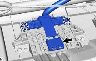
Disengage the 2 claws.
-
Disconnect the connector.
-
-
for LHD:
-
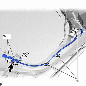
Disengage each clamp and remove the antenna cord sub-assembly.
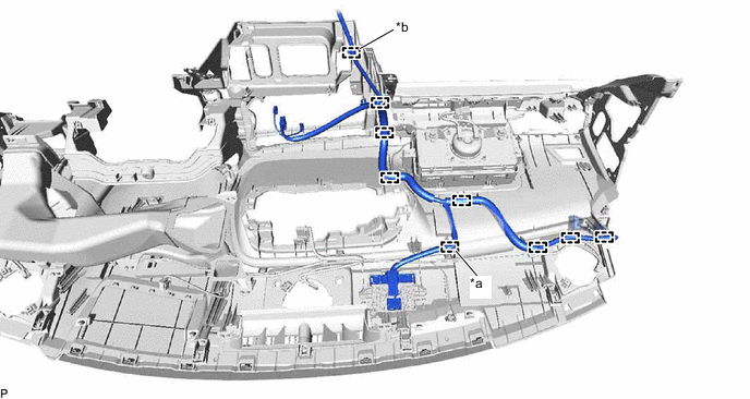
*a w/ Navigation Antenna *b w/ Telematics Transceiver
-
-
for RHD:
-
Disengage each clamp and remove the antenna cord sub-assembly.
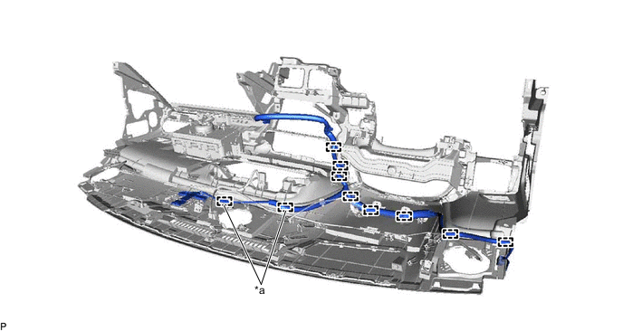
*a w/ Navigation Antenna - -
-
-
-
REMOVE ROOF HEADLINING ASSEMBLY
-
REMOVE NO. 2 ANTENNA CORD SUB-ASSEMBLY
-
w/o Television Antenna:
-
Remove the adhesive tape from the roof headlining assembly.
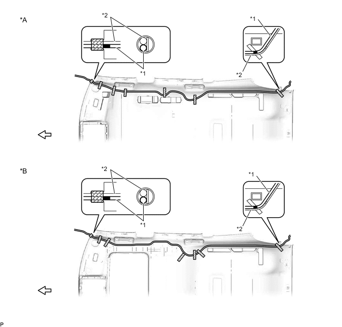
*A for Standard Roof *B for Sliding Roof *1 No. 2 Antenna Cord Sub-assembly *2 Washer Hose Assembly 
Adhesive Tape 
Front
-
-
w/ Television Antenna:
-
Remove the adhesive tape from the roof headlining assembly.
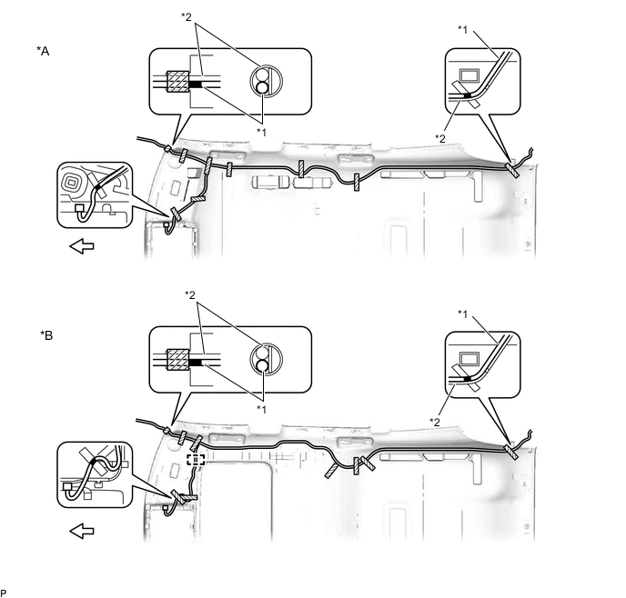
*A for Standard Roof *B for Sliding Roof *1 No. 2 Antenna Cord Sub-assembly *2 Washer Hose Assembly Adhesive Tape Front -
for Sliding Roof:
-
Disengage the clamp.
-
-
-
Remove the No. 2 antenna cord sub-assembly from the roof headlining assembly.
-
-
REMOVE NO. 5 ANTENNA CORD SUB-ASSEMBLY (for Type A)
-
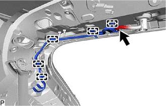
Disconnect each connector.
-
Disengage each clamp to remove the No. 5 antenna cord sub-assembly.
-
-
REMOVE NO. 6 ANTENNA CORD SUB-ASSEMBLY (for Type B)
-
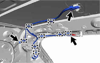
Disconnect each connector.
-
Disengage each clamp to remove the No. 6 antenna cord sub-assembly.
-
-
REMOVE BACK WINDOW UPPER PANEL TRIM
-
REMOVE BACK DOOR TRIM COVER LH
-
REMOVE BACK DOOR TRIM COVER RH
Tech Tips
Use the same procedure as for the LH side.
-
REMOVE BACK DOOR LOCK COVER
-
REMOVE BACK DOOR TRIM BASE
-
REMOVE DOOR PULL HANDLE
-
REMOVE NO. 1 LUGGAGE COMPARTMENT LIGHT ASSEMBLY
-
REMOVE BACK DOOR TRIM PANEL ASSEMBLY
-
REMOVE NO. 3 ANTENNA CORD SUB-ASSEMBLY
-
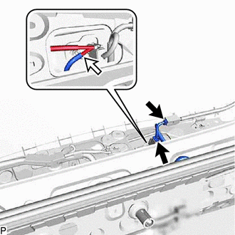
Disconnect the 2 connectors and washer hose.
-
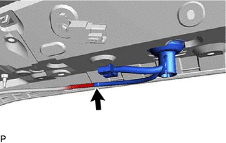
Disconnect the washer hose.
-
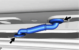
Disengage the 2 grommets and remove the No. 3 antenna cord sub-assembly.
-
-
REMOVE NO. 4 ANTENNA CORD SUB-ASSEMBLY
-
*a Clamp *b Guide Remove the bolt.
-
Disconnect each connector.
-
Disengage 3 clamps and 2 guides to remove the No. 4 antenna cord sub-assembly.
-