BRAKE BOOSTER(for LHD) INSTALLATION
PROCEDURE
-
INSTALL BRAKE BOOSTER GASKET
-
Install a new brake booster gasket to the brake booster assembly.
-
-
INSTALL BRAKE BOOSTER ASSEMBLY
-
Temporarily install the brake booster assembly to the vehicle body.
Note
Do not apply excessive force to the brake lines.
-
Temporarily install the lock nut and brake master cylinder push rod clevis to the brake booster assembly.
Note
Fully tighten the lock nut when adjusting the brake pedal height.
-
Install the 4 nuts to secure the brake booster assembly.
- Torque:
- 14 N*m { 143 kgf*cm, 10 ft.*lbf }
-
-
INSTALL PUSH ROD PIN
-
INSTALL BRAKE PEDAL RETURN SPRING
-
INSTALL BRAKE LINE
-
Install the 2 brake lines to the brake tube clamp.
Note
-
Do not kink or damage the brake lines.
-
Do not damage the clamp.
-
-
-
INSTALL AIR CONDITIONING HOSE AND ACCESSORY (w/ Rear Air Conditioning System)
-
Install the air conditioning hose and accessory with the nut.
- Torque:
- 9.8 N*m { 100 kgf*cm, 87 in.*lbf }
Note
-
Do not deform the refrigerant lines.
-
Do not damage the clamp.
-
-
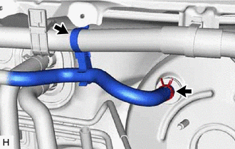
CONNECT FUEL VAPOR FEED HOSE ASSEMBLY (for 8AR-FTS)
-
Connect the fuel vapor feed hose assembly, and slide the clip to secure it.
-
-
CONNECT FUEL VAPOR FEED HOSE ASSEMBLY (for 2GR-FKS)
-
Connect the fuel vapor feed hose assembly, and slide the clip to secure it.
-
-
INSTALL ENGINE ROOM MAIN WIRE
-
for 8AR-FTS:
-
Install the engine room relay block assembly with the 2 bolts.
- Torque:
- 8.35 N*m { 85 kgf*cm, 74 in.*lbf }
-
Engage the clamp.
-
-
for 2GR-FKS:
-
Install the engine room relay block assembly with the 3 bolts.
- Torque:
- 8.35 N*m { 85 kgf*cm, 74 in.*lbf }
-
Engage the clamp.
-
-
Engage the clamp and pin to install the wire harness protector.
-
Install the bolt to secure the wire harness protector.
- Torque:
- 8.35 N*m { 85 kgf*cm, 74 in.*lbf }
-
w/ Security Horn Assembly:
-
Connect the connector to the security horn assembly.
-
-
for 8AR-FTS:
-
Connect the connector to the vacuum sensor assembly.
-
-
for 2GR-FKS:
-
Connect the connector to the vacuum warning switch assembly.
-
-
Engage the 6 clamps to install the engine room main wire.
-
for 8AR-FTS:
-
Engage the 2 clamps to install the engine wire.
-
Install the nut.
- Torque:
- 8.35 N*m { 85 kgf*cm, 74 in.*lbf }
-
-
-
INSTALL ECM (for 8AR-FTS)
-
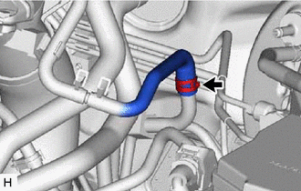
CONNECT UNION TO CHECK VALVE HOSE (for 8AR-FTS)
-
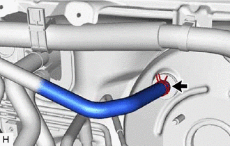
Connect the union to check valve hose to the brake booster assembly, and slide the clip to secure it.
-
-
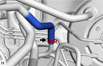
CONNECT UNION TO CHECK VALVE HOSE (for 2GR-FKS)
-
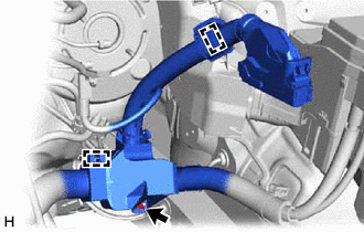
w/o Rear Air Conditioning System:
-
Connect the union to check valve hose to the brake booster assembly, and slide the clip to secure it.
-
Install the union to check valve hose to the engine room main wire.
-
-
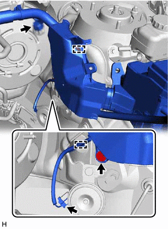
w/ Rear Air Conditioning System:
-
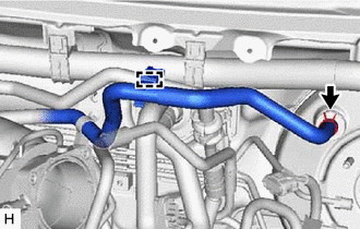
Connect the union to check valve hose to the brake booster assembly, and slide the clip to secure it.
-
Engage the clamp to install the union to check valve hose to the suction pipe sub-assembly.
-
-
-
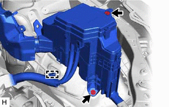
INSTALL RESERVOIR BRACKET
-
Install the reservoir bracket with the 2 bolts.
- Torque:
- 9.0 N*m { 92 kgf*cm, 80 in.*lbf }
-
-
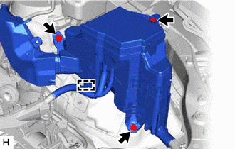
INSTALL BRAKE MASTER CYLINDER RESERVOIR ASSEMBLY
-
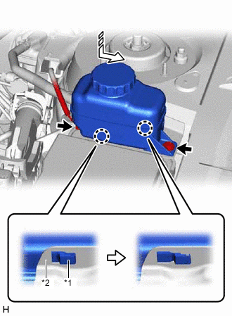
*1 Brake Master Cylinder Reservoir Assembly *2 Reservoir Bracket Move the brake master cylinder reservoir assembly as shown in the illustration to engage the 2 claws.
-
Connect the reservoir level switch connector and install the bolt.
- Torque:
- 9.0 N*m { 92 kgf*cm, 80 in.*lbf }
-
-
INSTALL OUTER COWL TOP PANEL SUB-ASSEMBLY
-
INSTALL FRONT WIPER MOTOR AND LINK ASSEMBLY
-
INSTALL NO. 1 INSTRUMENT PANEL UNDER COVER SUB-ASSEMBLY
-
INSTALL COWL SIDE TRIM BOARD LH
-
INSTALL FRONT DOOR SCUFF PLATE LH
w/o Rear No. 2 Seat: Click here
w/ Rear No. 2 Seat: Click here
-
INSTALL BRAKE MASTER CYLINDER SUB-ASSEMBLY WITH WAY
-
CONNECT CABLE TO NEGATIVE BATTERY TERMINAL
Note
When disconnecting the cable, some systems need to be initialized after the cable is reconnected.
-
INSPECT AND ADJUST BRAKE PEDAL