BRAKE ACTUATOR REMOVAL
CAUTION / NOTICE / HINT
The necessary procedures (adjustment, calibration, initialization, or registration) that must be performed after parts are removed, installed, or replaced during brake actuator assembly removal/installation are shown below.
| Replaced Part or Performed Procedure | Necessary Procedure | Effect/Inoperative Function when Necessary Procedure not Performed | Link |
|---|---|---|---|
| Battery terminal is disconnected/reconnected | Memorize steering angle neutral point | LKA/LDA System | |
| Pre-Crash Safety System | |||
| Lighting System (EXT)
|
|||
| Adaptive High Beam System | |||
| Parking Assist Monitor System (w/ Parallel Parking Assist Function) | |||
| Parking Assist Monitor System (w/o Parallel Parking Assist Function) | |||
| Panoramic View Monitor System | |||
| Drive the vehicle until stop and start control is permitted (approximately 15 to 60 minutes) | Stop and start system | ||
| Initialize back door lock | Power door lock control system | ||
| Reset back door close position | Power back door system | ||
| Replacement of brake actuator assembly | Operate the electric parking brake switch assembly | Parking brake indicator light (red) blinks when the engine switch is first turned on (IG) | |
| Perform yaw rate and acceleration sensor zero point calibration and store system information |
|
PROCEDURE
-
PRECAUTION
Note
After turning the engine switch off, waiting time may be required before disconnecting the cable from the negative (-) battery terminal. Therefore, make sure to read the disconnecting the cable from the negative (-) battery terminal notices before proceeding with work.
-
DISCONNECT CABLE FROM NEGATIVE BATTERY TERMINAL
Note
When disconnecting the cable, some systems need to be initialized after the cable is reconnected.
-
DRAIN BRAKE FLUID
Note
If brake fluid leaks onto any painted surface, immediately wash it off.
-
REMOVE BRAKE ACTUATOR WITH BRACKET
-
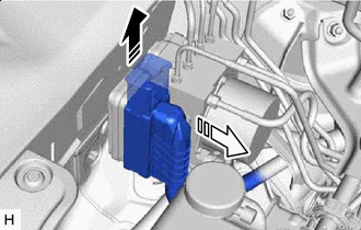

Release the lock lever 
Disconnect the connector Release the lock lever and disconnect the connector from the brake actuator assembly.
Note
Be careful not to allow any brake fluid to enter the connector.
-
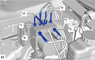
*a From 1st Chamber of Brake Master Cylinder Sub-assembly *b From 2nd Chamber of Brake Master Cylinder Sub-assembly *c To Front Wheel Cylinder Assembly RH *d To Rear Wheel Cylinder Assembly LH *e To Rear Wheel Cylinder Assembly RH *f To Front Wheel Cylinder Assembly LH Use tags or make a memo to identify the places to reconnect the brake lines.
-
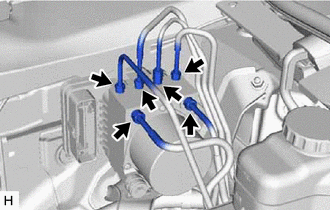
Using a union nut wrench, disconnect the 6 brake lines from the brake actuator assembly.
-
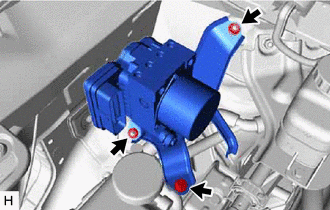
Remove the bolt, 2 nuts and brake actuator with bracket.
Note
-
Do not damage the brake lines.
-
Do not hold the brake actuator assembly by the connector.
Tech Tips
Remove the brake actuator with bracket while avoiding the brake lines.
-
-
-
REMOVE BRAKE ACTUATOR ASSEMBLY
-
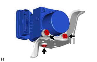
Remove the 3 bolts and brake actuator assembly from the brake actuator bracket assembly.
Note
Do not hold the brake actuator assembly by the connector.
-