INTELLIGENT CLEARANCE SONAR SYSTEM, Diagnostic DTC:U0232, U0233
| DTC Code | DTC Name |
|---|---|
| U0232 | Lost Communication with Blind Spot Monitor Slave Module |
| U0233 | Lost Communication with Blind Spot Monitor Master Module |
DESCRIPTION
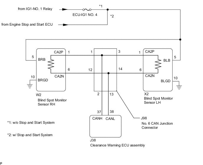
This DTC is stored when the blind spot monitor sensor LH judges that there is a communication problem with the blind spot monitor sensor RH.
| DTC No. | Detection Item | DTC Detection Condition | Trouble Area |
|---|---|---|---|
| U0232 | Lost Communication with Blind Spot Monitor Slave Module | The clearance warning ECU assembly cannot receive signals from the blind spot monitor sensor (slave) |
|
| U0233 | Lost Communication with Blind Spot Monitor Master Module | The clearance warning ECU assembly cannot receive signals from the blind spot monitor sensor (master) |
|
WIRING DIAGRAM
CAUTION / NOTICE / HINT
Note
-
Inspect the fuses for circuits related to this system before performing the following procedure.
-
Before measuring the resistance of the CAN bus, turn the engine switch off and leave the vehicle for 1 minute or more without operating the key or any switches, or opening or closing the doors. After that, disconnect the cable from the negative (-) battery terminal and leave the vehicle for 1 minute or more before measuring the resistance.
-
After turning the engine switch off, waiting time may be required before disconnecting the cable from the negative (-) battery terminal. Therefore, make sure to read the disconnecting the cable from the negative (-) battery terminal notices before proceeding with work.
Tech Tips
-
Operating the engine switch, any other switches or a door triggers related ECU and sensor communication on the CAN. This communication will cause the resistance value to change.
-
Even after DTCs are cleared, if a DTC is stored again after driving the vehicle for a while, the malfunction may be occurring due to vibration of the vehicle. In such a case, wiggling the ECUs or wire harness while performing the inspection below may help determine the cause of the malfunction.
PROCEDURE
-
CHECK DTC
-
Check for DTCs.
Body Electrical > IPA/ICS/Clearance Sonar > Trouble CodesResult Result Proceed to DTC U0232 is only output A DTC U0233 is only output B DTC U0232 and U0233 are output C
B 
CHECK CAN BUS MAIN WIRE Click here
C
CHECK CAN BUS MAIN WIRE (BLIND SPOT MONITOR SENSOR RH) Click here
A 
-
-
CHECK CAN BUS MAIN WIRE
-
Disconnect the cable from the negative (-) battery terminal.
-
Disconnect the W2 blind spot monitor sensor RH connector.
-
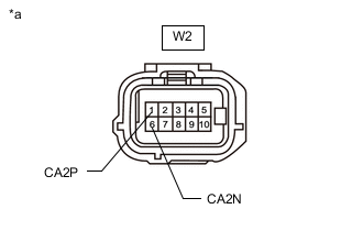
*a Front view of wire harness connector
(to blind spot monitor sensor RH)
Measure the resistance according to the value(s) in the table below.
Standard Resistance Tester Connection Condition Specified Condition W2-1 (CA2P) -W2-6 (CA2N) Cable disconnected from negative (-) battery terminal 108 to 132 Ω Result Proceed to OK NG
NG 
REPAIR OR REPLACE CAN MAIN WIRE OR CONNECTOR (BLIND SPOT MONITOR SENSOR RH - NO. 6 CAN JUNCTION CONNECTOR)
OK
-
-
CHECK HARNESS AND CONNECTOR (BLIND SPOT MONITOR SENSOR RH - BODY GROUND)
Result Proceed to OK NG
-
Measure the resistance according to the value(s) in the table below.
Standard Resistance Tester Connection Condition Specified Condition W2-10 (BRGD) - Body ground Always Below 1 Ω Result Proceed to OK NG
NG
REPAIR OR REPLACE CAN MAIN WIRE OR CONNECTOR (BLIND SPOT MONITOR SENSOR RH - NO. 6 CAN JUNCTION CONNECTOR)
OK
-
-
CHECK HARNESS AND CONNECTOR (BLIND SPOT MONITOR SENSOR RH POWER SOURCE)
Result Result Proceed to OK A NG (w/o Stop and Start System) B NG (w/ Stop and Start System) C
-
Disconnect the X2 blind spot monitor sensor LH connector.
-
Measure the voltage according to the value(s) in the table below.
Standard Voltage Tester Connection Condition Specified Condition X2-5 (BLB) - Body ground Engine switch on (IG) 11 to 14 V*1
10.5 to 16 V*2
X2-5 (BLB) - Body ground Engine switch off Below 1 V
-
*1: w/o Stop and Start System
-
*2: w/ Stop and Start System
Result Result Proceed to OK A NG (w/o Stop and Start System) B NG (w/ Stop and Start System) C -
A
REPLACE BLIND SPOT MONITOR SENSOR RH Click here
B
REPAIR OR REPLACE HARNESS OR CONNECTOR
C
GO TO STOP AND START SYSTEM Click here
-
-
CHECK CAN BUS MAIN WIRE
-
Disconnect the cable from the negative (-) battery terminal.
-
Disconnect the X2 blind spot monitor sensor LH connector.
-
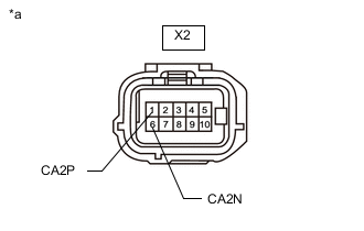
*a Front view of wire harness connector
(to blind spot monitor sensor LH)
Measure the resistance according to the value(s) in the table below.
Standard Resistance Tester Connection Condition Specified Condition X2-1 (CA2P) -X2-6 (CA2N) Cable disconnected from negative (-) battery terminal 108 to 132 Ω Result Proceed to OK NG
NG
REPAIR OR REPLACE CAN MAIN WIRE OR CONNECTOR (BLIND SPOT MONITOR SENSOR LH - NO. 6 CAN JUNCTION CONNECTOR)
OK
-
-
CHECK HARNESS AND CONNECTOR (BLIND SPOT MONITOR SENSOR LH - BODY GROUND)
Result Proceed to OK NG
-
Measure the resistance according to the value(s) in the table below.
Standard Resistance Tester Connection Condition Specified Condition X2-10 (BLGD) - Body ground Always Below 1 Ω Result Proceed to OK NG
NG
REPAIR OR REPLACE CAN MAIN WIRE OR CONNECTOR (BLIND SPOT MONITOR SENSOR RH - NO. 6 CAN JUNCTION CONNECTOR)
OK
-
-
CHECK HARNESS AND CONNECTOR (BLIND SPOT MONITOR SENSOR LH POWER SOURCE)
Result Result Proceed to OK A NG (w/o Stop and Start System) B NG (w/ Stop and Start System) C
-
Disconnect the X2 blind spot monitor sensor LH connector.
-
Measure the voltage according to the value(s) in the table below.
Standard Voltage Tester Connection Condition Specified Condition X2-5 (BLB) - Body ground Engine switch on (IG) 11 to 14 V*1
10.5 to 16 V*2
X2-5 (BLB) - Body ground Engine switch off Below 1 V
-
*1: w/o Stop and Start System
-
*2: w/ Stop and Start System
Result Result Proceed to OK A NG (w/o Stop and Start System) B NG (w/ Stop and Start System) C -
A
REPLACE BLIND SPOT MONITOR SENSOR LH Click here
B
REPAIR OR REPLACE HARNESS OR CONNECTOR
C
GO TO STOP AND START SYSTEM Click here
-
-
CHECK CAN BUS MAIN WIRE (BLIND SPOT MONITOR SENSOR RH)
-
Turn the engine switch off.
-
Disconnect the cable from the negative (-) battery terminal.
-
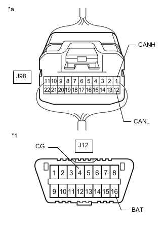
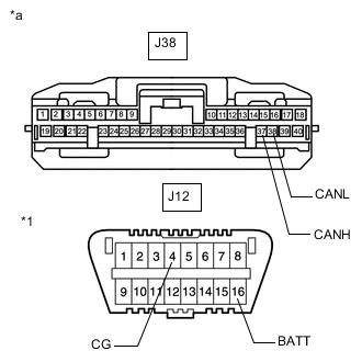
*1 DLC3 *a Component with harness connected
(No. 6 CAN Junction Connector)
Measure the resistance according to the value(s) in the table below.
Standard Resistance Tester Connection Condition Specified Condition Result J98-1 (CANH) -J98-12 (CANL) Cable disconnected from negative (-) battery terminal 54 to 69 Ω Below 54 Ω: Short circuit between bus lines 70 Ω or more: Open circuit in main bus lines J98-1(CANH) - J12-4 (CG) Cable disconnected from negative (-) battery terminal 200 Ω or higher Below 200 Ω: CANH short to ground J98-12(CANL) - J12-4 (CG) Cable disconnected from negative (-) battery terminal 200 Ω or higher Below 200 Ω: CANL short to ground J98-1(CANH) - J12-16 (BAT) Cable disconnected from negative (-) battery terminal 6 kΩ or higher Below 6 kΩ: CANH +B short J98-12(CANL) - J12-16 (BAT) Cable disconnected from negative (-) battery terminal 6 kΩ or higher Below 6 kΩ: CANL +B short Result Result Proceed to OK A Open circuit in CAN main bus lines B Short circuit between bus lines C
-
Short to ground
-
+B short
D -
B
CHECK FOR OPEN IN CAN BUS WIRE (NO. 6 CAN JUNCTION CONNECTOR) Click here
C
CHECK FOR SHORT IN CAN BUS WIRES (NO. 6 CAN JUNCTION CONNECTOR) Click here
D
CHECK FOR SHORT IN CAN BUS WIRES (NO. 6 CAN JUNCTION CONNECTOR) Click here
A
-
-
CONFIRM CAN BUS WIRE (CLEARANCE WARNING ECU ASSEMBLY)
-
Disconnect the J38 clearance warning ECU assembly connector.
-
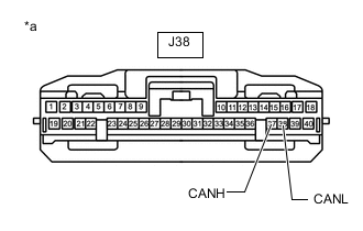
*a Front view of wire harness connector
(to clearance warning ECU assembly)
Measure the resistance according to the value(s) in the table below.
Standard Resistance Tester Connection Condition Specified Condition J38-37(CANH) - J38-38(CANL) Cable disconnected from negative (-) battery terminal 200 Ω or higher Result Proceed to OK NG
NG
REPAIR OR REPLACE CAN BUS WIRE (CLEARANCE WARNING ECU ASSEMBLY - NO. 6 CAN JUNCTION CONNECTOR)
OK
-
-
CHECK DTC
-
Clear the DTCs.
Body Electrical > IPA/ICS/Clearance Sonar > Clear DTCs -
Check for DTCs.
Body Electrical > IPA/ICS/Clearance Sonar > Trouble CodesResult Result Proceed to DTC U0232 and U0233 are output A DTC U0232 and U0233 are not output B
A
REPLACE CLEARANCE WARNING ECU ASSEMBLY for LHD: Click here for RHD: Click here
B
USE SIMULATION METHOD TO CHECK Click here
-
-
CHECK FOR OPEN IN CAN BUS WIRE (NO. 6 CAN JUNCTION CONNECTOR)
-
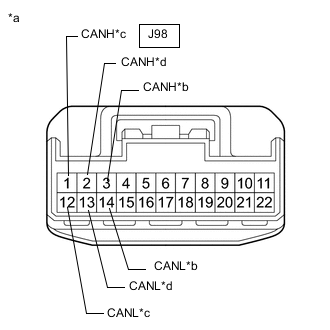
*a Front view of wire harness connector
(to No. 6 CAN Junction Connector)
*b to blind spot monitor sensor LH CAN main wire *c to blind spot monitor sensor RH CAN main wire *d to clearance warning ECU assembly CAN wire Disconnect the J98 No. 6 CAN junction connector.
-
Measure the resistance according to the value(s) in the table below.
Standard Resistance Tester Connection Condition Specified Condition J98-3 (CANH) - J98-14(CANL) Cable disconnected from negative (-) battery terminal 108 to 132 Ω J98-1 (CANH) - J98-12(CANL) Cable disconnected from negative (-) battery terminal 108 to 132 Ω J98-2 (CANH) - J98-13 (CANL) Cable disconnected from negative (-) battery terminal 200 Ω or higher Result Result Proceed to OK A NG (to blind spot monitor sensor LH CAN main wire) B NG (to blind spot monitor sensor RH CAN main wire) C NG (to clearance warning ECU assembly CAN wire) D
A
REPLACE NO. 6 CAN JUNCTION CONNECTOR
C
CHECK FOR OPEN IN CAN BUS MAIN WIRE (BLIND SPOT MONITOR SENSOR RH) Click here
D
CHECK FOR OPEN IN CAN BUS WIRE (CLEARANCE WARNING ECU ASSEMBLY) Click here
B
-
-
CHECK FOR OPEN IN CAN BUS MAIN WIRE (BLIND SPOT MONITOR SENSOR LH)
-
Reconnect the J98 No. 6 CAN junction connector.
-
*a Front view of wire harness connector
(to blind spot monitor sensor LH)
Disconnect the X2 blind spot monitor sensor LH connector.
-
Measure the resistance according to the value(s) in the table below.
Standard Resistance Tester Connection Condition Specified Condition X2-1 (CA2P) - X2-6 (CA2N) Cable disconnected from negative (-) battery terminal 108 to 132 Ω Result Proceed to OK NG
OK
REPLACE BLIND SPOT MONITOR SENSOR LH Click here
NG
REPAIR OR REPLACE CAN MAIN WIRE OR CONNECTOR (BLIND SPOT MONITOR SENSOR LH - NO. 6 CAN JUNCTION CONNECTOR)
-
-
CHECK FOR OPEN IN CAN BUS MAIN WIRE (BLIND SPOT MONITOR SENSOR RH)
-
Reconnect the J98 No. 6 CAN junction connector.
-
*a Front view of wire harness connector
(to blind spot monitor sensor RH)
Disconnect the W2 blind spot monitor sensor RH connector.
-
Measure the resistance according to the value(s) in the table below.
Standard Resistance Tester Connection Condition Specified Condition W2-1 (CA2P) -W2-6 (CA2N) Cable disconnected from negative (-) battery terminal 108 to 132 Ω Result Proceed to OK NG
OK
REPLACE BLIND SPOT MONITOR SENSOR RH Click here
NG
REPAIR OR REPLACE CAN MAIN WIRE OR CONNECTOR (BLIND SPOT MONITOR SENSOR RH - NO. 6 CAN JUNCTION CONNECTOR)
-
-
CHECK FOR OPEN IN CAN BUS WIRE (CLEARANCE WARNING ECU ASSEMBLY)
-
Reconnect the J98 No. 6 CAN junction connector.
-
*a Front view of wire harness connector
(to clearance warning ECU assembly)
Disconnect the J38 clearance warning ECU connector.
-
Measure the resistance according to the value(s) in the table below.
Standard Resistance Tester Connection Condition Specified Condition J38-37(CANH) - J38-38(CANL) Cable disconnected from negative (-) battery terminal 54 to 69 Ω Result Proceed to OK NG
OK
REPLACE CLEARANCE WARNING ECU ASSEMBLY for LHD: Click here for RHD: Click here
NG
REPAIR OR REPLACE CAN BUS WIRE (CLEARANCE WARNING ECU ASSEMBLY - NO. 6 CAN JUNCTION CONNECTOR)
-
-
CHECK FOR SHORT IN CAN BUS WIRES (NO. 6 CAN JUNCTION CONNECTOR)
-
*a Front view of wire harness connector
(to No. 6 CAN Junction Connector)
*b to blind spot monitor sensor LH CAN main wire *c to blind spot monitor sensor RH CAN main wire *d to clearance warning ECU assembly CAN wire Disconnect the J98 No. 6 CAN junction connector.
-
Measure the resistance according to the value(s) in the table below.
Standard Resistance Tester Connection Condition Specified Condition J98-3 (CANH) - J98-14(CANL) Cable disconnected from negative (-) battery terminal 108 to 132 Ω J98-1 (CANH) - J98-12(CANL) Cable disconnected from negative (-) battery terminal 108 to 132 Ω J98-2 (CANH) - J98-13(CANL) Cable disconnected from negative (-) battery terminal 200 Ω or higher Result Result Proceed to OK A NG (to blind spot monitor sensor LH CAN main wire) B NG (to blind spot monitor sensor RH CAN main wire) C NG (to clearance warning ECU assembly CAN wire) D
A
REPLACE NO. 6 CAN JUNCTION CONNECTOR
C
CHECK FOR SHORT IN CAN BUS WIRES (BLIND SPOT MONITOR SENSOR RH) Click here
D
CHECK FOR SHORT IN CAN BUS WIRES (CLEARANCE WARNING ECU ASSEMBLY) Click here
B
-
-
CHECK FOR SHORT IN CAN BUS WIRES (BLIND SPOT MONITOR SENSOR LH)
-
Reconnect the J98 No. 6 CAN junction connector.
-
*a Front view of wire harness connector
(to blind spot monitor sensor LH)
Disconnect the X2 blind spot monitor sensor LH connector.
-
Measure the resistance according to the value(s) in the table below.
Standard Resistance Tester Connection Condition Specified Condition X2-1 (CA2P) - X2-6 (CA2N) Cable disconnected from negative (-) battery terminal 108 to 132 Ω Result Proceed to OK NG
OK
REPLACE BLIND SPOT MONITOR SENSOR LH Click here
NG
REPAIR OR REPLACE CAN MAIN WIRE OR CONNECTOR (BLIND SPOT MONITOR SENSOR LH - NO. 6 CAN JUNCTION CONNECTOR)
-
-
CHECK FOR SHORT IN CAN BUS WIRES (BLIND SPOT MONITOR SENSOR RH)
-
Reconnect the J98 No. 6 CAN junction connector.
-
*a Front view of wire harness connector
(to blind spot monitor sensor RH)
Disconnect the W2 blind spot monitor sensor RH connector.
-
Measure the resistance according to the value(s) in the table below.
Standard Resistance Tester Connection Condition Specified Condition W2-1 (CA2P) -W2-6 (CA2N) Cable disconnected from negative (-) battery terminal 108 to 132 Ω Result Proceed to OK NG
OK
REPLACE BLIND SPOT MONITOR SENSOR RH Click here
NG
REPAIR OR REPLACE CAN MAIN WIRE OR CONNECTOR (BLIND SPOT MONITOR SENSOR RH - NO. 6 CAN JUNCTION CONNECTOR)
-
-
CHECK FOR SHORT IN CAN BUS WIRES (CLEARANCE WARNING ECU ASSEMBLY)
-
Reconnect the J98 No. 6 CAN junction connector.
-
*a Front view of wire harness connector
(to clearance warning ECU assembly)
Disconnect the J38 clearance warning ECU connector.
-
Measure the resistance according to the value(s) in the table below.
Standard Resistance Tester Connection Condition Specified Condition J38-37(CANH) - J38-38(CANL) Cable disconnected from negative (-) battery terminal 54 to 69 Ω Result Proceed to OK NG
OK
REPLACE CLEARANCE WARNING ECU ASSEMBLY for LHD: Click here for RHD: Click here
NG
REPAIR OR REPLACE CAN BUS WIRE (CLEARANCE WARNING ECU ASSEMBLY - NO. 6 CAN JUNCTION CONNECTOR)
-
-
CHECK FOR SHORT IN CAN BUS WIRES (NO. 6 CAN JUNCTION CONNECTOR)
-
Disconnect the J98 No. 6 CAN junction connector.
-
Measure the resistance according to the value(s) in the table below.
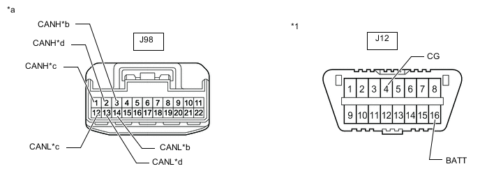
*1 DLC3 - - *a Front view of wire harness connector
(to No. 5 CAN Junction Connector)
*b to blind spot monitor sensor LH CAN main wire *c to blind spot monitor sensor RH CAN main wire *d to clearance warning ECU assembly CAN wire Standard Resistance Tester Connection Condition Specified Condition J98-3 (CANH) - J12-4 (CG) Cable disconnected from negative (-) battery terminal 200 Ω or higher J98-14 (CANL) - J12-4 (CG) Cable disconnected from negative (-) battery terminal 200 Ω or higher J98-3 (CANH) - J12-16 (BAT) Cable disconnected from negative (-) battery terminal 6 kΩ or higher J98-14 (CANL) - J12-16 (BAT) Cable disconnected from negative (-) battery terminal 6 kΩ or higher J98-1 (CANH) - J12-4 (CG) Cable disconnected from negative (-) battery terminal 200 Ω or higher J98-12 (CANL) - J12-4 (CG) Cable disconnected from negative (-) battery terminal 200 Ω or higher J98-1 (CANH) - J12-16 (BAT) Cable disconnected from negative (-) battery terminal 6 kΩ or higher J98-12 (CANL) - J12-16 (BAT) Cable disconnected from negative (-) battery terminal 6 kΩ or higher J98-2 (CANH) - J12-4 (CG) Cable disconnected from negative (-) battery terminal 200 Ω or higher J98-13 (CANL) - J12-4 (CG) Cable disconnected from negative (-) battery terminal 200 Ω or higher J98-2 (CANH) - J12-16 (BAT) Cable disconnected from negative (-) battery terminal 6 kΩ or higher J98-13 (CANL) - J12-16 (BAT) Cable disconnected from negative (-) battery terminal 6 kΩ or higher Result Result Proceed to OK A NG (to blind spot monitor sensor LH CAN main wire) B NG (to blind spot monitor sensor RH CAN main wire) C NG (to clearance warning ECU assembly CAN wire) D
A
REPLACE NO. 6 CAN JUNCTION CONNECTOR
C
CHECK FOR SHORT IN CAN BUS WIRES (BLIND SPOT MONITOR SENSOR RH) Click here
D
CHECK FOR SHORT IN CAN BUS WIRES (CLEARANCE WARNING ECU ASSEMBLY) Click here
B
-
-
CHECK FOR SHORT IN CAN BUS WIRES (BLIND SPOT MONITOR SENSOR LH)
-
Reconnect the J98 No. 6 CAN junction connector.
-
Disconnect the X2 blind spot monitor sensor LH connector.
-

*1 DLC3 *a Front view of wire harness connector
(to blind spot monitor sensor LH)
Measure the resistance according to the value(s) in the table below.
Standard Resistance Tester Connection Condition Specified Condition X2-1 (CA2P) - J12-4 (CG) Cable disconnected from negative (-) battery terminal 200 Ω or higher X2-6 (CA2N) - J12-4 (CG) Cable disconnected from negative (-) battery terminal 200 Ω or higher X2-1 (CA2P) - J12-16 (BAT) Cable disconnected from negative (-) battery terminal 6 kΩ or higher X2-6 (CA2N) - J12-16 (BAT) Cable disconnected from negative (-) battery terminal 6 kΩ or higher Result Proceed to OK NG
OK
REPLACE BLIND SPOT MONITOR SENSOR LH Click here
NG
REPAIR OR REPLACE CAN MAIN WIRE OR CONNECTOR (BLIND SPOT MONITOR SENSOR LH - NO. 6 CAN JUNCTION CONNECTOR)
-
-
CHECK FOR SHORT IN CAN BUS WIRES (BLIND SPOT MONITOR SENSOR RH)
-
Reconnect the J98 No. 6 CAN junction connector.
-
Disconnect the W2 blind spot monitor sensor RH connector.
-
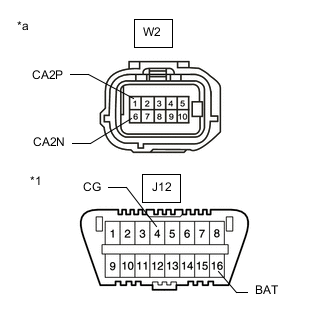
*1 DLC3 *a Front view of wire harness connector
(to blind spot monitor sensor RH)
Measure the resistance according to the value(s) in the table below.
Standard Resistance Tester Connection Condition Specified Condition W2-1 (CA2P) - J12-4 (CG) Cable disconnected from negative (-) battery terminal 200 Ω or higher W2-6 (CA2N) - J12-4 (CG) Cable disconnected from negative (-) battery terminal 200 Ω or higher W2-1 (CA2P) - J12-16 (BAT) Cable disconnected from negative (-) battery terminal 6 kΩ or higher W2-6 (CA2N) - J12-16 (BAT) Cable disconnected from negative (-) battery terminal 6 kΩ or higher Result Proceed to OK NG
OK
REPLACE BLIND SPOT MONITOR SENSOR RH Click here
NG
REPAIR OR REPLACE CAN MAIN WIRE OR CONNECTOR (BLIND SPOT MONITOR SENSOR RH - NO. 6 CAN JUNCTION CONNECTOR)
-
-
CHECK FOR SHORT IN CAN BUS WIRES (CLEARANCE WARNING ECU ASSEMBLY)
-
Reconnect the J98 No. 6 CAN junction connector.
-
*1 DLC3 *a Front view of wire harness connector
(to clearance warning ECU assembly)
Disconnect the J38 clearance warning ECU connector.
-
Measure the resistance according to the value(s) in the table below.
Standard Resistance Tester Connection Condition Specified Condition J38-37 (CANH) - J12-4 (CG) Cable disconnected from negative (-) battery terminal 200 Ω or higher J38-38 (CANL) - J12-4 (CG) Cable disconnected from negative (-) battery terminal 200 Ω or higher J38-37 (CANH) - J12-16 (BAT) Cable disconnected from negative (-) battery terminal 6 kΩ or higher J38-38 (CANL) - J12-16 (BAT) Cable disconnected from negative (-) battery terminal 6 kΩ or higher Result Proceed to OK NG
OK
REPLACE CLEARANCE WARNING ECU ASSEMBLY for LHD: Click here for RHD: Click here
NG
REPAIR OR REPLACE CAN BUS WIRE (CLEARANCE WARNING ECU ASSEMBLY - NO. 6 CAN JUNCTION CONNECTOR)
-