REAR AXLE CARRIER(for 2WD) INSTALLATION
CAUTION / NOTICE / HINT
Tech Tips
-
Use the same procedure for the RH side and LH side.
-
The following procedure is for the LH side.
PROCEDURE
-
TEMPORARILY INSTALL REAR AXLE CARRIER SUB-ASSEMBLY
-
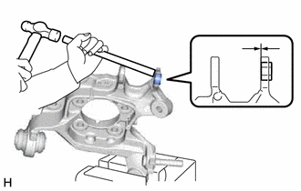
Secure the rear axle carrier sub-assembly in a vise using aluminum plates.
Note
Do not overtighten the vise.
-
Using a brass bar and a hammer, push out the bushing until it is positioned as shown in the illustration.
Tech Tips
Pushing out the bushing makes it easier to install the rear axle carrier sub-assembly.
-
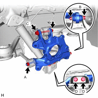
Temporarily install the rear axle carrier sub-assembly to the rear No. 1 suspension arm assembly with the spacer and nut (A).
Note
Fully tighten the nut (A) after stabilizing the suspension.
-
Install the rear axle carrier sub-assembly to the rear No. 2 suspension arm assembly with the bolt (B) and nut.
- Torque:
- 100 N*m { 1020 kgf*cm, 74 ft.*lbf }
Note
-
Insert the bolt with the threaded end facing the front of the vehicle.
-
Because the nut has its own stopper, do not turn the nut. Tighten the bolt with the nut secured.
-
Install the rear axle carrier sub-assembly to the rear upper control arm assembly with the bolt (C) and nut.
- Torque:
- 145 N*m { 1479 kgf*cm, 107 ft.*lbf }
Note
-
Insert the bolt with the threaded end facing the rear of the vehicle.
-
Because the nut has its own stopper, do not turn the nut. Tighten the bolt with the nut secured.
-
Install the rear axle carrier sub-assembly to the rear lower shock absorber bracket sub-assembly with the 2 bolts (D).
- Torque:
- 100 N*m { 1020 kgf*cm, 74 ft.*lbf }
-
Slowly lower the rear No. 2 suspension arm assembly.
-
-
INSTALL REAR TRAILING ARM ASSEMBLY
-
INSTALL NO. 2 PARKING BRAKE WIRE ASSEMBLY
-
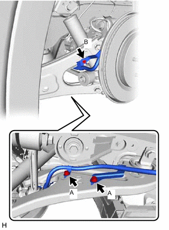
Install the No. 2 parking brake wire assembly to the rear trailing arm assembly with the 3 bolts.
- Torque:
- Bolt (A)
- 15 N*m { 153 kgf*cm, 11 ft.*lbf }
- Bolt (B)
- 8.5 N*m { 87 kgf*cm, 75 in.*lbf }
-
-
INSTALL REAR AXLE HUB AND BEARING ASSEMBLY
-
INSTALL REAR NO. 1 SKID CONTROL SENSOR WIRE
-
INSTALL REAR DISC
-
INSTALL REAR DISC BRAKE CALIPER ASSEMBLY
-
INSTALL REAR FLEXIBLE HOSE
-
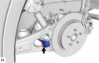
Install the rear flexible hose to the rear upper control arm assembly with the bolt.
- Torque:
- 18.8 N*m { 192 kgf*cm, 14 ft.*lbf }
-
-
STABILIZE SUSPENSION
-
INSTALL REAR NO. 1 SUSPENSION ARM ASSEMBLY
-
Install the rear No. 1 suspension arm assembly with the nut.
- Torque:
- 145 N*m { 1479 kgf*cm, 107 ft.*lbf }
-
-
INSTALL REAR SUSPENSION ARM COVER
-
INSTALL REAR WHEEL
-
INSPECT AND ADJUST REAR WHEEL ALIGNMENT
-
CHECK FOR SPEED SENSOR SIGNAL
-
PERFORM INITIALIZATION
Parking assist monitor system (w/ Parallel Parking Assist Function) for Initialization: Click here
for Calibration: Click here
Parking assist monitor system (w/o Parallel Parking Assist Function) for Initialization: Click here
for Calibration: Click here
Panoramic view monitor system for Initialization: Click here
for Calibration: Click here
-
Adaptive high beam system
-
Automatic headlight beam level control system
-