FRONT DRIVE SHAFT ASSEMBLY REMOVAL

CAUTION / NOTICE / HINT
The necessary procedures (adjustment, calibration, initialization, or registration) that must be performed after parts are removed and installed, or replaced during front drive shaft assembly removal/installation are shown below.
| Replaced Part or Performed Procedure | Necessary Procedure | Effect/Inoperative Function when Necessary Procedure not Performed | Link |
|---|---|---|---|
| Front wheel alignment adjustment | Perform the following procedures in the order shown:
|
|
|
|
Bleed the oil pump assembly with motor (automatic transaxle assembly) | Stop and start system |
*2: w/ Stop and Start System
Tech Tips
-
Use the same procedure for the RH side and LH side.
-
The following procedure is for the LH side.
PROCEDURE
-
REMOVE FRONT WHEELS
-
REMOVE FRONT WHEEL OPENING EXTENSION PAD LH
for 8AR-FTS:
for 2GR-FKS:
-
REMOVE NO. 3 ENGINE UNDER COVER
for 8AR-FTS:
for 2GR-FKS:
-
REMOVE FRONT FENDER APRON SEAL LH
for 8AR-FTS:
for 2GR-FKS:
-
DRAIN AUTOMATIC TRANSAXLE FLUID
for U661E:
for U661F:
for U881E:
for U881F:
-
DRAIN TRANSFER OIL (for AWD)
-
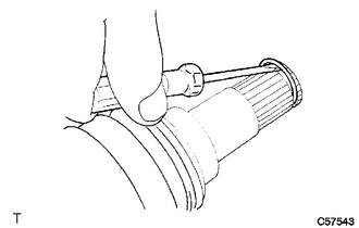
REMOVE FRONT AXLE SHAFT NUT
-
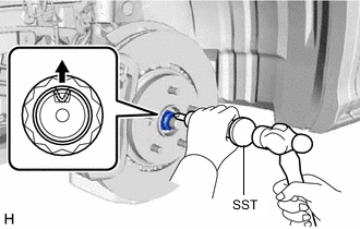
Using SST and a hammer, release the staked part of the front axle shaft nut.
- SST
- 09930-00010
Note
Fully loosen the staked part of the front axle shaft nut, otherwise the threads of the drive shaft may be damaged.
-
While applying the brakes, remove the front axle shaft nut.
-
-
SEPARATE FRONT SPEED SENSOR (w/o AVS)
-
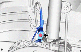
Remove the bolt and separate the front flexible hose and sensor clamp.
-
Disengage the 2 claws to separate the sensor clamp.
-
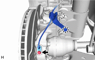
Remove the bolt and separate the front speed sensor from the steering knuckle.
Note
-
Keep the tip of the front speed sensor and installation hole free of foreign matter.
-
Do not rotate or apply excessive force to the front speed sensor when removing it from the steering knuckle. Rotating or applying excessive force may result in damage to the front speed sensor.
-
-
-
SEPARATE FRONT SPEED SENSOR (w/ AVS)
-
Remove the bolt and separate the front flexible hose and sensor clamp.
-
Disconnect the connector from the front shock absorber assembly.
-
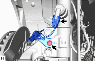
Remove the bolt and separate the front skid control sensor wire from the front shock absorber assembly.
-

Remove the bolt and separate the front speed sensor from the steering knuckle.
Note
-
Keep the tip of the front speed sensor and installation hole free of foreign matter.
-
Do not rotate or apply excessive force to the front speed sensor when removing it from the steering knuckle. Rotating or applying excessive force may result in damage to the front speed sensor.
-
-
-
SEPARATE TIE ROD ASSEMBLY
-
SEPARATE FRONT STABILIZER LINK ASSEMBLY
-
SEPARATE FRONT LOWER NO. 1 SUSPENSION ARM SUB-ASSEMBLY
-
SEPARATE FRONT DRIVE SHAFT ASSEMBLY
-
REMOVE FRONT DRIVE SHAFT ASSEMBLY LH
-
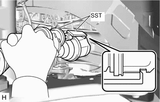
Using SST, remove the front drive shaft assembly LH.
- SST
- 09520-01010
- 09520-24010 ( 09520-32040 )
Note
-
Do not damage the front drive shaft oil seal LH.
-
Do not damage the front axle inboard joint boot.
-
Do not drop the front drive shaft assembly LH.
-
-
REMOVE FRONT DRIVE SHAFT ASSEMBLY RH (for 2WD)
-

Separate the bearing bracket hole snap ring from the drive shaft bearing bracket.
-
Remove the No. 1 drive shaft bearing bracket setting bolt and front drive shaft assembly RH from the drive shaft bearing bracket.
Note
-
Do not damage the front drive shaft oil seal RH.
-
Do not damage the front axle inboard joint boot.
-
Do not drop the front drive shaft assembly RH.
Tech Tips
If it is difficult to disengage the fitting, tap the end of the front drive inboard joint assembly with a brass bar and a hammer.
-
-
Remove the bearing bracket hole snap ring from the front drive shaft assembly RH.
-
-
REMOVE FRONT DRIVE SHAFT ASSEMBLY RH (for AWD)
-

Separate the bearing bracket hole snap ring from the transfer assembly.
-
Remove the No. 1 drive shaft bearing bracket setting bolt and front drive shaft assembly RH from the transfer assembly.
Note
-
Do not damage the transfer case oil seal RH.
-
Do not damage the front axle inboard joint boot.
-
Do not drop the front drive shaft assembly RH.
Tech Tips
If it is difficult to disengage the fitting, tap the end of the front drive inboard joint assembly with a brass bar and a hammer.
-
-
Remove the bearing bracket hole snap ring from the front drive shaft assembly RH.
-
-
REMOVE FRONT DRIVE SHAFT HOLE SNAP RING (for LH Side)
-
Using a screwdriver, remove the front drive shaft hole snap ring.
-