TRANSFER ASSEMBLY INSPECTION

PROCEDURE
-
INSPECT PRELOAD
-
Inspect Driven Pinion Preload:
-
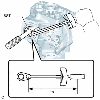
*a Torque Wrench Fulcrum Length Using SST and a torque wrench, measure the preload of the backlash between the driven pinion and ring gear.
- SST
- 09326-20011
Preload (at Starting) 0.5 to 0.9 N*m (5 to 9 kgf*cm, 4 to 8 in.*lbf) Tech Tips
-
Calculate the torque wrench reading when changing the fulcrum length of the torque wrench.
-
When using SST (fulcrum length of 50 mm (1.97 in.)) + torque wrench (fulcrum length of 130 mm (5.12 in.)):
0.3 to 0.6 N*m (3 to 6 kgf*cm, 3 to 5 in.*lbf)
-
-
Inspect Total Preload:
-
Using SST and a torque wrench, measure the total preload.
- SST
- 09326-20011
Preload (at Starting) 0.3 to 0.5 N*m (3 to 5 kgf*cm, 3 to 4 in.*lbf) + Driven pinion preload Tech Tips
-
Calculate the torque wrench reading when changing the fulcrum length of the torque wrench.
-
When using SST (fulcrum length of 50 mm (1.97 in.)) + torque wrench (fulcrum length of 130 mm (5.12 in.)):
0.22 to 0.36 N*m (2.2 to 3.7 kgf*cm, 1.9 to 3.2 in.*lbf) + Driven pinion preload
-
-
-
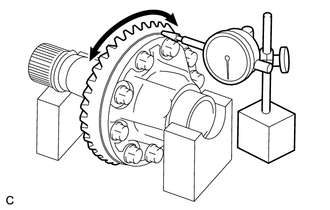
INSPECT RING GEAR BACKLASH
-
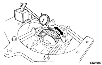
Set a dial indicator perpendicular to a ring gear tooth tip.
-
Using a dial indicator, check the ring gear backlash.
Backlash 0.14 to 0.25 mm (0.00551 to 0.00984 in.) If the backlash is not within the specification, adjust the side bearing preload or repair as necessary.
Note
Check at least 3 positions on the circumference of the ring gear.
-
-
INSPECT TOOTH CONTACT BETWEEN RING GEAR AND DRIVEN PINION
-
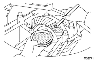
Apply a light coat of Prussian blue evenly to both sides of all teeth.
-
Rotate the ring gear 10 times or more.
-
Rotate the ring gear to inspect the tooth contact pattern.
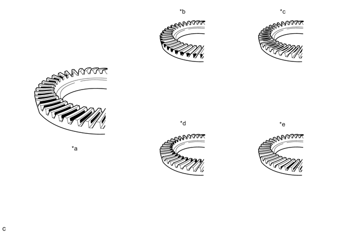
*a Proper Contact *b Heel Contact *c Face Contact *d Toe Contact *e Flank Contact - - Note
Check at least 4 positions on the circumference of the ring gear.
Tech Tips
Prussian blue shown in the illustration indicates the tooth contact pattern.
-
If the tooth contact pattern is not correct, select a new transfer output shaft washer that is thicker or thinner as necessary and recheck.
-
-
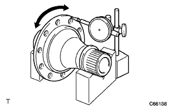
INSPECT RUNOUT OF RING GEAR
-
Place the transfer ring gear mounting case with ring gear on the V-blocks.
-
Using a dial indicator, check the runout of the ring gear.
Maximum Runout 0.06 mm (0.00236 in.)
-
-
INSPECT TRANSFER RING GEAR MOUNTING CASE
-
Place the transfer ring gear mounting case on the V-blocks.
-
Using a dial indicator, check the runout of the ring gear mounting case.
Maximum Runout 0.04 mm (0.00157 in.)
-