SHIFT PADDLE SWITCH REMOVAL
CAUTION / NOTICE / HINT
The necessary procedures (adjustment, calibration, initialization or registration) that must be performed after parts are removed and installed, or replaced during shift paddle switch (transmission shift switch assembly) removal/installation are shown below.
| Replacement Part or Performed Procedure | Necessary Procedure | Effect/Inoperative Function when Necessary Procedure not Performed | Link |
|---|---|---|---|
| Battery terminal is disconnected/reconnected | Memorize steering angle neutral point | LKA/LDA System | |
| Intelligent clearance sonar system*1 | |||
| Pre-crash safety system | |||
| Lighting system (EXT)
|
|||
| Adaptive high beam system | |||
| Drive the vehicle until stop and start control is permitted (approximately 15 to 60 minutes) | Stop and start system | ||
| Memorize steering angle neutral point | Parking Assist Monitor System (w/ Parallel Parking Assist Function) | ||
| Parking Assist Monitor System (w/o Parallel Parking Assist Function) | |||
| Panoramic view monitor system | |||
| Initialize back door lock | Power door lock control system | ||
| Reset back door close position | Power back door system |
*1: When performing learning using the GTS.
PROCEDURE
-
REMOVE STEERING WHEEL ASSEMBLY
-
REMOVE CRUISE CONTROL MAIN SWITCH
-
REMOVE STEERING PAD SWITCH ASSEMBLY
-
REMOVE LOWER NO. 1 STEERING WHEEL BOSS COVER
-
Remove the 2 screws.
-
Disengage the 2 claws and remove the 2 lower No. 1 steering wheel boss covers from the steering wheel assembly.
-
-
REMOVE SHIFT PADDLE SWITCH (TRANSMISSION SHIFT SWITCH ASSEMBLY)
-
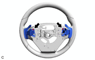
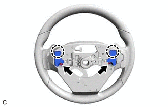
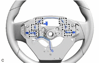
Remove the 2 screws.
-
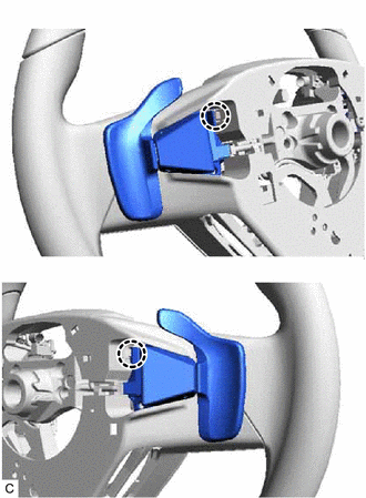
Disengage the 2 claws and separate the 2 shift paddle switches (transmission shift switch assemblies) from the steering wheel assembly.
-
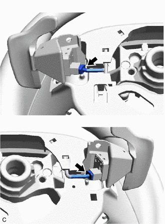
Disconnect the 2 shift paddle switch (transmission shift switch assembly) connectors to remove the 2 shift paddle switches (transmission shift switch assemblies) from the No. 1 switch wire.
-
-
REMOVE NO. 1 SWITCH WIRE
Tech Tips
Perform this procedure only when replacement of the No. 1 switch wire is necessary.
-
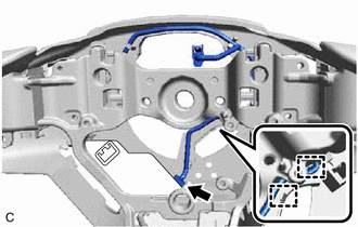
Disconnect the steering vibration and heater ECU connector.
-
Disengage the 2 guides.
-
Disengage the 6 clamps and remove the No. 1 switch wire from the steering wheel assembly.
-