THERMOSTAT(for Cylinder Block) REMOVAL
CAUTION / NOTICE / HINT
The necessary procedures (adjustment, calibration, initialization or registration) that must be performed after parts are removed and installed, or replaced during thermostat (for Cylinder Block) removal/installation are shown below.
| Replaced Part or Performed Procedure | Necessary Procedure | Effect/Inoperative Function when Necessary Procedure not Performed | Link |
|---|---|---|---|
| Battery terminal is disconnected/reconnected | Memorize steering angle neutral point | LKA /LDA system | |
| Pre-crash safety system | |||
| Lighting system (EXT)
|
|||
| Adaptive high beam system | |||
| Drive the vehicle until stop and start control is permitted (approximately 15 to 60 minutes) | Stop and start system | ||
| Memorize steering angle neutral point | Parking assist monitor system (w/ Parallel parking assist function) | ||
| Parking assist monitor system (w/o Parallel parking assist function) | |||
| Panoramic view monitor system | |||
| Initialize back door lock | Power door lock control system | ||
| Reset back door close position | Power back door system | ||
|
Front television camera view adjustment | Panoramic view monitor system | Click here for Initialization Click here for Calibration |
|
Inspection After Repair |
|
PROCEDURE
-
DRAIN ENGINE COOLANT
-
REMOVE TURBOCHARGER SUB-ASSEMBLY
-
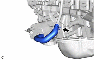
DISCONNECT NO. 2 RADIATOR HOSE
-
REMOVE COMPRESSOR ASSEMBLY WITH PULLEY
-
REMOVE NO. 1 COMPRESSOR MOUNTING BRACKET
-
Remove the 2 bolts, 2 nuts and No. 1 compressor mounting bracket.
-
-
REMOVE ENGINE OIL LEVEL DIPSTICK GUIDE
-
Remove the engine oil level dipstick.
-
Remove the 2 bolts and engine oil level dipstick guide.
-
Remove the O-ring from the engine oil level dipstick guide.
-
-
REMOVE NO. 3 EXHAUST MANIFOLD HEAT INSULATOR
-
Remove the 2 bolts and No. 3 exhaust manifold heat insulator.
-
-
REMOVE NO. 4 EXHAUST MANIFOLD HEAT INSULATOR
-
Remove the 2 bolts and No. 4 exhaust manifold heat insulator.
-
-
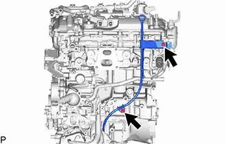
REMOVE NO. 1 WATER BY-PASS PIPE
-
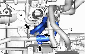
*1 Water Hose Sub-assembly *2 No. 2 Water By-pass Hose *3 No. 7 Water By-pass Hose Slide the clip and disconnect the water hose sub-assembly from the No. 1 water by-pass pipe.
-
Slide the clip and disconnect the No. 2 water by-pass hose from the No. 1 water by-pass pipe.
-
Slide the clip and disconnect the No. 7 water by-pass hose from the No. 1 water by-pass pipe.
-
Slide the clip and disconnect the No. 5 water by-pass hose from the No. 1 water by-pass pipe.
-
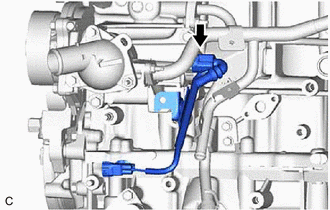
Disconnect the oil pressure switching valve assembly connector.
-
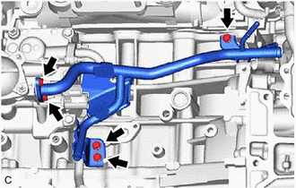
Remove the 3 bolts, 2 nuts, No. 1 water by-pass pipe and gasket.
-
-
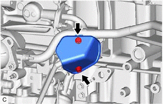
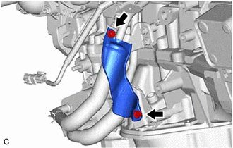
REMOVE NO. 4 WATER BY-PASS PIPE
-
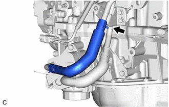
Slide the clip and disconnect the No. 4 water by-pass hose from the No. 4 water by-pass pipe.
-
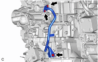
Remove the bolt, 2 nuts, No. 4 water by-pass pipe and gasket.
-
-
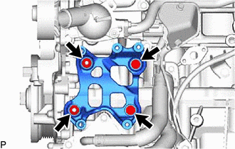
REMOVE WATER INLET HOUSING
-
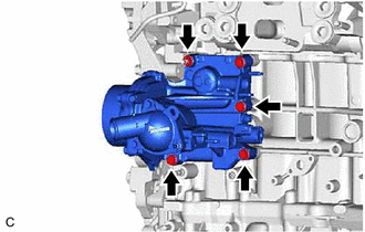
Remove the 4 bolts, nut, water inlet housing and 3 gaskets.
-
-
REMOVE THERMOSTAT (for Cylinder Block)
-
Remove the thermostat (for Cylinder Block) from the cylinder block assembly.
-
Remove the gasket from the thermostat (for Cylinder Block).
-