FUEL PUMP(for High Pressure) REMOVAL
CAUTION / NOTICE / HINT
The necessary procedures (adjustment, calibration, initialization or registration) that must be performed after parts are removed and installed, or replaced during fuel pump assembly removal/installation are shown below.
| Replaced Part or Performed Procedure | Necessary Procedure | Effect/Inoperative Function when Necessary Procedure not Performed | Link |
|---|---|---|---|
| Battery terminal is disconnected/reconnected | Memorize steering angle neutral point | LKA/LDA System | |
| Intelligent clearance sonar system*1 | |||
| Pre-crash safety system | |||
| Lighting system (EXT)
|
|||
| Adaptive high beam system | |||
| Drive the vehicle until stop and start control is permitted (approximately 15 to 60 minutes) | Stop and start system | ||
| Memorize steering angle neutral point | Parking Assist Monitor System (w/ Parallel Parking Assist Function) | ||
| Parking Assist Monitor System (w/o Parallel Parking Assist Function) | |||
| Panoramic view monitor system | |||
| Initialize back door lock | Power door lock control system | ||
| Reset back door close position | Power back door system | ||
|
Inspection After Repair |
|
w/ Canister Pump Module: Click here w/o Canister Pump Module: Click here |
Click here Click here
PROCEDURE
-
PRECAUTION
Note
After turning the engine switch off, waiting time may be required before disconnecting the cable from the negative (-) battery terminal. Therefore, make sure to read the disconnecting the cable from the negative (-) battery terminal notices before proceeding with work.
-
DISCHARGE FUEL SYSTEM PRESSURE
-
DISCONNECT CABLE FROM NEGATIVE BATTERY TERMINAL
Note
When disconnecting the cable, some systems need to be initialized after the cable is reconnected.
-
REMOVE INTAKE MANIFOLD
-
REMOVE NO. 2 ENGINE UNDER COVER
-
REMOVE FUEL PUMP PROTECTOR
-
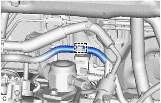
Disengage the clamp to disconnect the fuel tube sub-assembly from the fuel pump protector.
-
Remove the 2 bolts and fuel pump protector from the cylinder head sub-assembly.
-
-
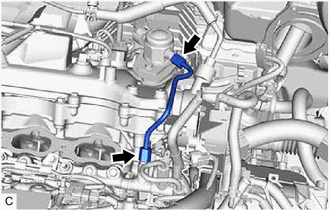
DISCONNECT NO. 2 FUEL TUBE SUB-ASSEMBLY
-
Disconnect the No. 2 fuel tube sub-assembly from the fuel pump assembly.
-
-
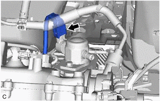
REMOVE NO. 1 FUEL PIPE SUB-ASSEMBLY
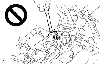
CAUTION:
To prevent serious injury due to fuel spray from the high-pressure fuel lines, always discharge fuel system pressure before removing any fuel system components.
-
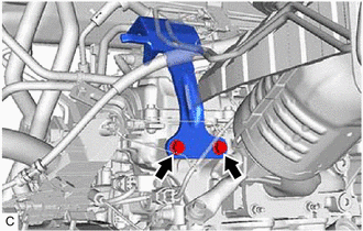
Using a 17 mm union nut wrench, loosen the 2 union nuts of the No. 1 fuel pipe sub-assembly.
-
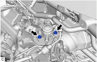
Loosen the 2 bolts of the fuel pump assembly.
-
Remove the No. 1 fuel pipe sub-assembly from the fuel delivery pipe RH and fuel pump assembly.
-
-
REMOVE FUEL PUMP ASSEMBLY
-
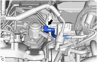
Disconnect the fuel pump assembly connector.
-
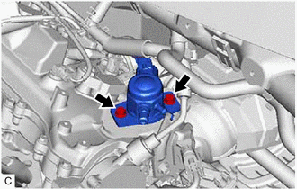
Remove the 2 bolts, fuel pump assembly and fuel pump lifter guide from the cylinder head cover sub-assembly.
-
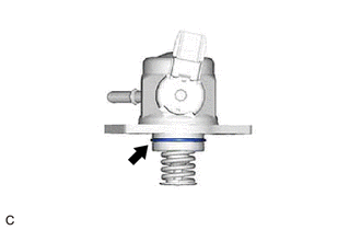
Remove the O-ring from the fuel pump assembly.
-
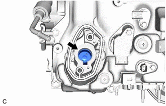
Remove the fuel pump lifter assembly from the fuel pump lifter housing.
-
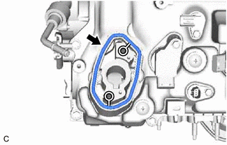
Remove the fuel pump spacer gasket from the cylinder head cover sub-assembly.
-