FUEL INJECTOR(for Port Injection) REMOVAL

CAUTION / NOTICE / HINT
The necessary procedures (adjustment, calibration, initialization or registration) that must be performed after parts are removed and installed, or replaced during fuel injector assembly removal/installation are shown below.
| Replaced Part or Performed Procedure | Necessary Procedure | Effect/Inoperative Function when Necessary Procedure not Performed | Link |
|---|---|---|---|
| Battery terminal is disconnected/reconnected | Memorize steering angle neutral point | LKA/LDA System | |
| Intelligent clearance sonar system*1 | |||
| Pre-crash safety system | |||
| Lighting system (EXT)
|
|||
| Adaptive high beam system | |||
| Drive the vehicle until stop and start control is permitted (approximately 15 to 60 minutes) | Stop and start system | ||
| Memorize steering angle neutral point | Parking Assist Monitor System (w/ Parallel Parking Assist Function) | ||
| Parking Assist Monitor System (w/o Parallel Parking Assist Function) | |||
| Panoramic view monitor system | |||
| Initialize back door lock | Power door lock control system | ||
| Reset back door close position | Power back door system | ||
|
Inspection After Repair |
|
w/ Canister Pump Module: Click here w/o Canister Pump Module: Click here |
Click here Click here
PROCEDURE
-
PRECAUTION
Note
After turning the engine switch off, waiting time may be required before disconnecting the cable from the negative (-) battery terminal. Therefore, make sure to read the disconnecting the cable from the negative (-) battery terminal notices before proceeding with work.
-
DISCHARGE FUEL SYSTEM PRESSURE
-
DISCONNECT CABLE FROM NEGATIVE BATTERY TERMINAL
Note
When disconnecting the cable, some systems need to be initialized after the cable is reconnected.
-
REMOVE INTAKE AIR SURGE TANK ASSEMBLY
-
DISCONNECT FUEL TUBE SUB-ASSEMBLY
-
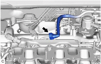
Disconnect the fuel tube sub-assembly from the fuel delivery pipe sub-assembly.
-
-
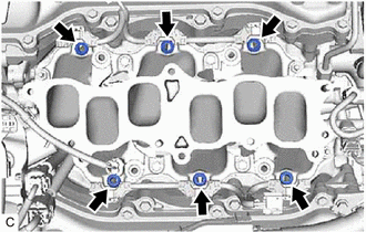
REMOVE FUEL DELIVERY PIPE SUB-ASSEMBLY
-
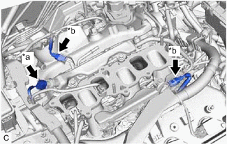
*a Fuel Pressure Sensor Connector *b No. 5 Engine Wire Connector Disconnect the fuel pressure sensor connector.
-
Disconnect the 2 No. 5 engine wire connectors.
-
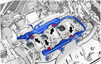
Remove the 4 bolts and fuel delivery pipe sub-assembly with the 6 fuel injector assemblies from the intake manifold.
Note
-
Be careful not to drop the fuel injector assemblies when removing the fuel delivery pipe sub-assembly.
-
When removing the fuel delivery pipe sub-assembly, hold the pipe by both ends and pull it straight upward.
-
-
-
REMOVE NO. 1 DELIVERY PIPE SPACER
-
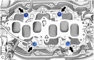
Remove the 4 No. 1 delivery pipe spacers from the intake manifold.
-
-
REMOVE INJECTOR VIBRATION INSULATOR
-
Remove the 6 injector vibration insulators from the intake manifold.
-
-
REMOVE FUEL INJECTOR ASSEMBLY
-
for Bank 2:
-
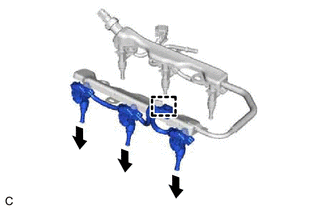
Disengage the clamp to disconnect the No. 5 engine wire from the fuel delivery pipe sub-assembly.
-
Pull the 3 fuel injector assemblies out of the fuel delivery pipe sub-assembly.
-
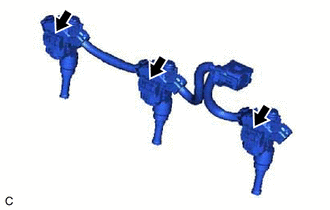
Disconnect the 3 fuel injector assembly connectors.
-
-
for Bank 1:
-
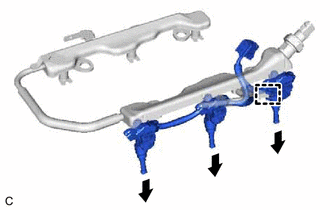
Disengage the clamp to disconnect the No. 5 engine wire from the fuel delivery pipe sub-assembly.
-
Pull the 3 fuel injector assemblies out of the fuel delivery pipe sub-assembly.
-
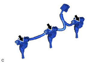
Disconnect the 3 fuel injector assembly connectors.
-
-
Remove the O-ring from each fuel injector assembly.
-
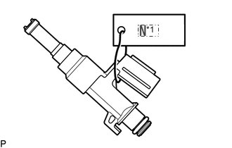
*1 No. 1 Attach a tag or label with the corresponding cylinder number to each fuel injector assembly so that they can be installed to their original locations.
Note
Cover the fuel injector assemblies with plastic bags to prevent damage and contamination.
-