FUEL PUMP REMOVAL

CAUTION / NOTICE / HINT
The necessary procedures (adjustment, calibration, initialization or registration) that must be performed after parts are removed and installed, or replaced during fuel pump removal/installation are shown below.
| Replaced Part or Performed Procedure | Necessary Procedure | Effect/Inoperative Function when Necessary Procedure not Performed | Link |
|---|---|---|---|
| Battery terminal is disconnected/reconnected | Memorize steering angle neutral point | LKA/LDA System | |
| Pre-crash safety system | |||
| Lighting system (EXT)
|
|||
| Adaptive high beam system | |||
| Drive the vehicle until stop and start control is permitted (approximately 15 to 60 minutes) | Stop and start system | ||
| Memorize steering angle neutral point | Parking Assist Monitor System (w/ Parallel Parking Assist Function) | ||
| Parking Assist Monitor System (w/o Parallel Parking Assist Function) | |||
| Panoramic view monitor system | |||
| Initialize back door lock | Power door lock control system | ||
| Reset back door close position | Power back door system | ||
| Replacement of fuel pump | Inspection After Repair |
|
w/ Canister Pump Module: Click here w/o Canister Pump Module: Click here |
PROCEDURE
-
PRECAUTION
Note
After turning the engine switch off, waiting time may be required before disconnecting the cable from the negative (-) battery terminal. Therefore, make sure to read the disconnecting the cable from the negative (-) battery terminal notices before proceeding with work.
-
DISCHARGE FUEL SYSTEM PRESSURE
-
DISCONNECT CABLE FROM NEGATIVE BATTERY TERMINAL
Note
When disconnecting the cable, some systems need to be initialized after the cable is reconnected.
-
REMOVE REAR DOOR SCUFF PLATE LH
-
REMOVE REAR DOOR SCUFF PLATE RH
Tech Tips
Use the same procedure as for the LH side.
-
REMOVE REAR SEAT ASSEMBLY LH
-
REMOVE REAR SEAT ASSEMBLY RH
-
REMOVE UPPER QUARTER TRIM PAD LH
-
REMOVE REAR SEAT SIDE GARNISH LH
-
REMOVE UPPER QUARTER TRIM PAD RH
Tech Tips
Use the same procedure as for the LH side.
-
REMOVE REAR SEAT SIDE GARNISH RH
Tech Tips
Use the same procedure as for the LH side.
-
REMOVE REAR FLOOR SERVICE HOLE COVER
-
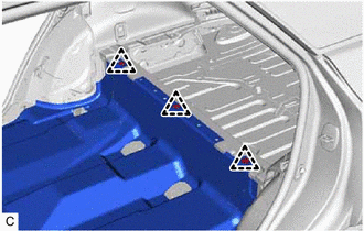
Remove the 3 clips and turn back the front floor carpet assembly.
-
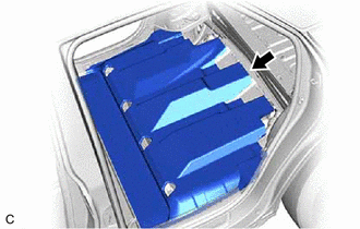
Turn back the rear floor silencer.
-
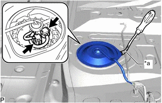
*a Protective Tape Using a clip remover with its tip wrapped with protective tape, remove the rear floor service hole cover and butyl tape.
-
Disconnect the 2 fuel pump connectors.
-
-
DISCONNECT FUEL TANK MAIN TUBE SUB-ASSEMBLY
-
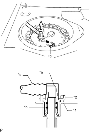
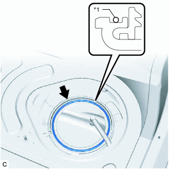
*1 Fuel Suction Plate Sub-assembly *2 Tube Joint Clip *a Fuel Tube Joint *b O-ring *c Nylon Tube 
Pull off 
Pull off Remove the tube joint clip, and pull off the fuel tube joint of the fuel tank main tube sub-assembly.
Note
-
Remove any foreign matter on the fuel tube joint before performing this work.
-
Do not scratch or allow any foreign matter to get on the parts when disconnecting them as the fuel tube connector has O-rings that seal the pipe (fuel pipe).
-
Be sure to disconnect the fuel tube joint by hand.
-
Do not bend, twist, pinch or kink the nylon tube.
-
Cover the disconnected fuel tube joint with a plastic bag to prevent damage and contamination.
-
If the fuel tube joint and fuel suction plate sub-assembly are stuck, push and pull to release them.
-
-
-
REMOVE FUEL PUMP GAUGE RETAINER
Note
Before performing these procedures, first cover the connectors and fuel tube joint of the fuel suction tube with pump and gauge assembly with vinyl tape and then clean any dirt and foreign matter in order to prevent contamination of the fuel system.
-
Install SST (fuel pump holding tool assy) to the fuel pump gauge retainer.
-
Insert SST (claw No. 1) between the service hole and fuel pump gauge retainer as shown in the illustration.
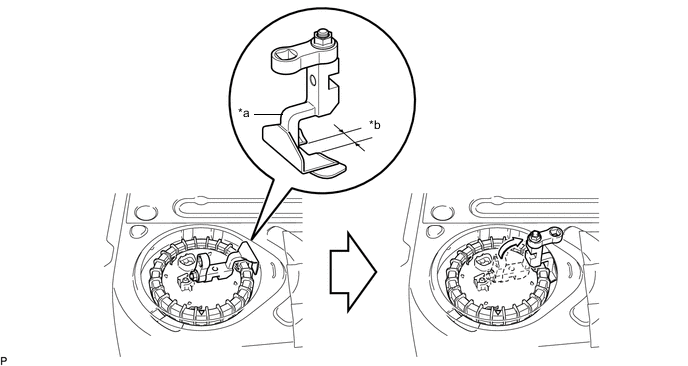
*a SST (Claw No. 1) *b Wide - SST
- 09808-14050 ( 09882-14050 )
-
Align the detent of the tank suction tube support and cutout of SST (claw No. 1).
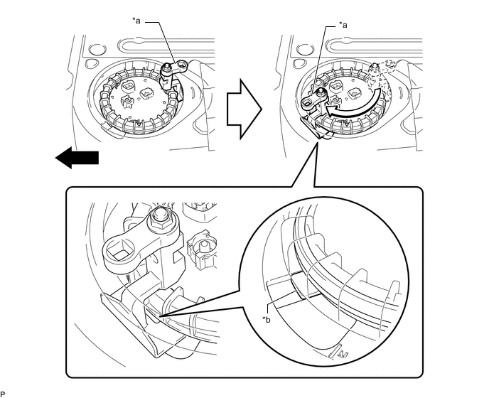
*a SST (Claw No. 1) *b Detent of Tank Suction Tube Support Front - - -
Insert SST (claw) between the service hole and fuel pump gauge retainer as shown in the illustration.
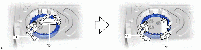
*a SST (Claw No. 1) *b SST (Claw) - SST
- 09808-14040 ( 09882-14040 )
-
Insert SST (claw No. 2) between the service hole and fuel pump gauge retainer, and align it with the second detent of the tank suction tube support.
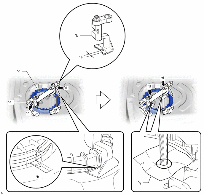
*a SST (Claw No. 1) *b SST (Claw No. 2) *c SST (Bridge) *d SST (Bolt) *e Narrow *f Contact *g Cloth *h Detent of Tank Suction Tube Support - SST
- 09808-14050 ( 09881-14050, 09882-14050, 09883-14050, 09884-14050 )
-
Install SST (bridge) to SST (claw No. 1) and SST (claw No. 2) with 2 SST (bolt).
-
Place a piece of cloth or equivalent on the fuel suction tube with pump and gauge assembly and lightly tighten 2 SST (bolt) of SST (bridge) until they come into contact with the fuel suction tube with pump and gauge assembly.
Note
If a piece of cloth or equivalent is not placed between the fuel suction tube with pump and gauge assembly and 2 SST (bolt), the fuel suction tube with pump and gauge assembly may be damaged.
-
-
Install SST (fuel pump retainer tool assy) to the fuel pump gauge retainer.
-
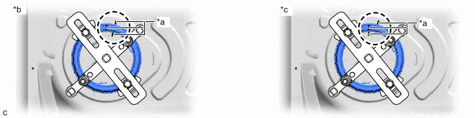
Position SST (claw) next to SST (claw No. 1) so that the protrusions of the fuel pump gauge retainer are aligned with the grooves of SST (claw). Insert the second SST (claw) between the service hole and fuel pump gauge retainer, and position it next to SST (claw No. 2) so that it is opposite to SST (claw), and the protrusions of the fuel pump gauge retainer are aligned with the grooves of SST (claw).
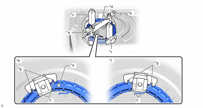
*a SST (Claw No. 1) *b SST (Claw No. 2) *c SST (Claw) *d SST (Bridge) *e Triangle Mark *f Protrusion of Fuel Pump Gauge Retainer *g Groove of SST (Claw) *h Correct *i Incorrect - - - SST
- 09808-14040 ( 09882-14040 )
Note
Ensure that SST (claw) does not cover the triangle mark of the fuel pump gauge retainer.
-
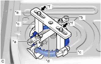
*a SST (Claw No. 1) *b SST (Claw No. 2) *c SST (Claw) *d SST (Bridge) *e SST (Plate) *f SST (Bolt and Washer Set) While ensuring that SST (plate) is centered, install SST (plate) to 2 SST (claw) with 2 SST (bolt and washer set).
- SST
- 09808-14040 ( 09881-14040, 09883-14040 )
-
-
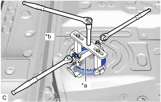
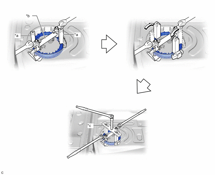
*a SST (Fuel Pump Holding Tool Assy) *b SST (Fuel Pump Retainer Tool Assy) Attach 2 breaker bars to SST (fuel pump holding tool assy) and 1 breaker bar to SST (fuel pump retainer tool assy).
-

*a Paint Mark Place paint marks on the fuel suction tube with pump and gauge assembly, fuel pump gauge retainer and fuel tank assembly as shown in the illustration.
-
While holding the 2 breaker bars attached to SST (fuel pump holding tool assy), turn the breaker bar attached to SST (fuel pump retainer tool assy) to loosen the fuel pump gauge retainer. [*1]
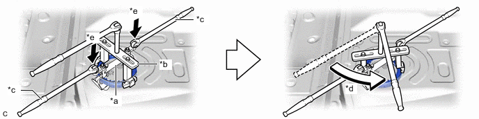
*a SST (Fuel Pump Holding Tool Assy) *b SST (Fuel Pump Retainer Tool Assy) *c Holding *d Turn *e Push down - - Note
Push down on the 2 locations shown in the illustration to prevent SST (fuel pump holding tool assy) from turning.
-
Check that only the paint mark on the fuel pump gauge retainer has moved.
*a Paint Mark *b Correct *c Incorrect - - Tech Tips
If the paint mark on the fuel suction tube with pump and gauge assembly has also moved, tighten the fuel pump gauge retainer until the paint marks are aligned at the original position. Then repeat from step [*1].
-
Loosen the fuel pump gauge retainer by using SST (fuel pump retainer tool assy) until the fuel pump gauge retainer turns approximately 360°.
*a SST (Claw) *b SST (Fuel Pump Holding Tool Assy) *c SST (Fuel Pump Retainer Tool Assy) - - -
Remove SST (fuel pump retainer tool assy) and SST (fuel pump holding tool assy) from the fuel pump gauge retainer.
-
Check that the fuel pump gauge retainer can be loosened by hand.
- SST
- 09808-14040 ( 09881-14040, 09882-14040, 09883-14040 )
-
While holding the fuel suction tube with pump and gauge assembly by hand, remove the fuel pump gauge retainer.
-
-
REMOVE FUEL SUCTION TUBE WITH PUMP AND GAUGE ASSEMBLY
-
Remove the fuel suction tube with pump and gauge assembly from the fuel tank assembly.
Note
Be careful not to bend the arm of the fuel sender gauge assembly.
-
*1 Fuel Suction Tube Set Gasket Remove the fuel suction tube set gasket from the fuel tank assembly.
-