ENGINE UNIT REMOVAL

CAUTION / NOTICE / HINT
The necessary procedures (adjustment, calibration, initialization, or registration) that must be performed after parts are removed and installed, or replaced during engine unit removal/installation are shown below.
| Replaced Part or Performed Procedure | Necessary Procedure | Effect/Inoperative Function when Necessary Procedure not Performed | Link | |
|---|---|---|---|---|
| Disconnect cable from negative battery terminal | Memorize steering angle neutral point | LKA/LDA System | ||
| Intelligent clearance sonar system*2 | ||||
| Pre-crash safety system | ||||
| Lighting system (EXT)
|
||||
| Adaptive high beam system | ||||
| Parking Assist Monitor System (w/ Parallel Parking Assist Function) | ||||
| Parking Assist Monitor System (w/o Parallel Parking Assist Function) | ||||
| Panoramic view monitor system | ||||
| Initialize back door lock | Power door lock control system | |||
| Reset back door close position | Power back door system | |||
| Replacement of ECM | Perform Vehicle Identification Number (VIN) or frame number registration |
|
for 2GR-FKS (w/ Canister Pump Module): for 2GR-FKS (w/o Canister Pump Module) |
|
| ECU Communication ID Registration (Immobiliser system) | Engine start function | See Service Bulletin for the registration method. | ||
| Perform code registration (Immobiliser system) |
|
|||
| Replacement of ECM (If possible, read the transaxle compensation code from the previous ECM) |
Possible to read transaxle compensation code | Perform the following procedures in the order shown:
|
|
Click here for Initialization (U881E) Click here for Registration (U881E) Click here for Initialization (U881F) Click here for Registration (U881F) |
| Impossible to read transaxle compensation code | Perform the following procedures in the order shown:
|
|||
w/ Canister Pump Module |
Inspection After Repair |
|
||
w/o Canister Pump Module |
Inspection After Repair |
|
||
| Replacement of automatic transaxle assembly | Perform the following procedures in the order shown:
|
|
for U881E Initialization: for U881E Registration: for U881F Initialization: for U881F Registration: |
|
| Front wheel alignment adjustment |
|
|
||
| Suspension, tires, etc. (The vehicle height changes because of suspension or tire replacement) |
|
|
||
| Rear television camera assembly optical axis (Back camera position setting) | Parking assist monitor system (w/ Parallel Parking Assist Function) | for Initialization: for Calibration: |
||
| Parking assist monitor system (w/o Parallel Parking Assist Function) | for Initialization: for Calibration: |
|||
|
Panoramic view monitor system | for Initialization: for Calibration: |
||
| Initialize headlight ECU sub-assembly LH |
|
|||
*2: When performing learning using the GTS.
Click here Click here
PROCEDURE
-
REMOVE KNOCK CONTROL SENSOR
-
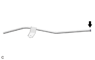
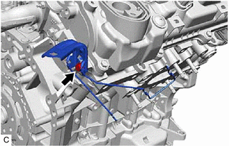
REMOVE SENSOR WIRE
-
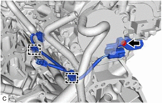
Disengage the 2 clamps and remove the bolt and sensor wire from the water inlet pipe.
-
-
REMOVE IGNITION COIL ASSEMBLY
-
REMOVE VACUUM PUMP ASSEMBLY
-
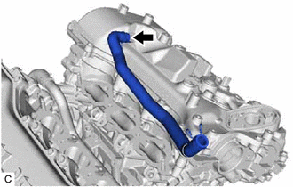
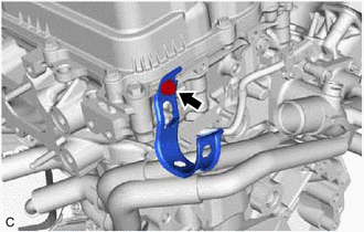
REMOVE NO. 3 WATER BY-PASS HOSE
-
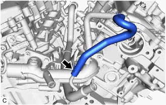
Slide the clip and remove the No. 3 water by-pass hose from the water inlet pipe.
-
-
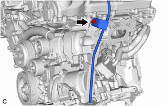
REMOVE NO. 2 WATER BY-PASS HOSE
-
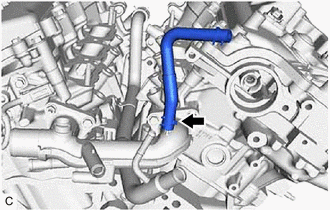
Slide the clip and remove the No. 2 water by-pass hose from the water outlet.
-
-
REMOVE VENTILATION HOSE
-
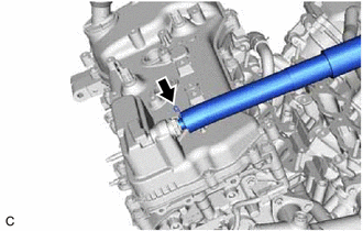
Slide the clip and remove the ventilation hose from the PCV valve (ventilation valve sub-assembly).
-
-
REMOVE NO. 2 VENTILATION HOSE
-
Slide the clip and remove the No. 2 ventilation hose from the cylinder head cover sub-assembly.
-
-
REMOVE V-RIBBED BELT
-
REMOVE GENERATOR ASSEMBLY
-
for 180A Type:
-
for 150A Type:
-
-
REMOVE COMPRESSOR AND MAGNETIC CLUTCH
-
REMOVE NO. 1 COMPRESSOR MOUNTING BRACKET
-
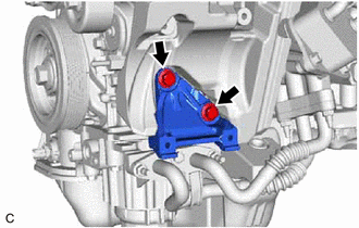
Remove the 2 bolts and No. 1 compressor mounting bracket from the cylinder block sub-assembly.
-
-
REMOVE NO. 2 IDLER PULLEY SUB-ASSEMBLY
-
REMOVE V-RIBBED BELT TENSIONER ASSEMBLY
-
REMOVE WATER PUMP PULLEY
-
REMOVE ENGINE OIL LEVEL DIPSTICK GUIDE
-
Remove the engine oil level dipstick from the engine oil level dipstick guide.
-
Remove the bolt and engine oil level dipstick guide from the camshaft housing sub-assembly LH and oil pan sub-assembly.
-
Remove the engine oil level dipstick guide O-ring from the engine oil level dipstick guide.
-
-
REMOVE NO. 5 CYLINDER BLOCK INSULATOR (w/ Oil Cooler)
-
Remove the No. 5 cylinder block insulator from the engine assembly.
-
-
REMOVE DRIVE SHAFT BEARING BRACKET (for 2WD)
-
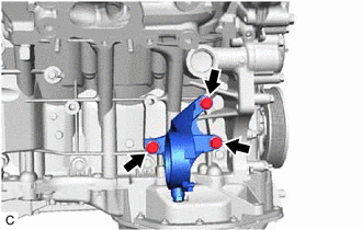
Remove the 3 bolts and drive shaft bearing bracket from the cylinder block sub-assembly.
-
-
REMOVE NO. 2 TRANSFER STIFFENER PLATE (for AWD)
-
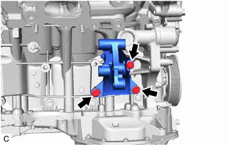
Remove the 3 bolts and No. 2 transfer stiffener plate from the cylinder block sub-assembly.
-
-
REMOVE NO. 1 EXHAUST PIPE SUPPORT BRACKET
-
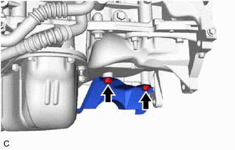
Remove the 2 bolts and No. 1 exhaust pipe support bracket from the oil pan sub-assembly.
-
-
REMOVE WIRE HARNESS CLAMP BRACKET
-
Remove the bolt and wire harness clamp bracket from the camshaft housing sub-assembly.
-
-
REMOVE RADIATOR PIPE CLAMP
-
Remove the bolt and radiator pipe clamp from the camshaft housing sub-assembly LH.
-
-
REMOVE STUD BOLT
Note
If a stud bolt is deformed or its threads are damaged, replace it.
-
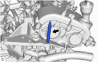
Using an 8 mm socket wrench, remove the stud bolt from the front No. 1 engine mounting bracket LH.
-