FUEL PRESSURE SENSOR(for High Pressure) REMOVAL
CAUTION / NOTICE / HINT
The necessary procedures (adjustment, calibration, initialization or registration) that must be performed after parts are removed and installed, or replaced during fuel pressure sensor removal/installation are shown below.
| Replaced Part or Performed Procedure | Necessary Procedure | Effect/Inoperative Function when Necessary Procedure not Performed | Link |
|---|---|---|---|
| Battery terminal is disconnected/reconnected | Memorize steering angle neutral point | LKA/LDA System | |
| Intelligent clearance sonar system*1 | |||
| Pre-crash safety system | |||
| Lighting system (EXT)
|
|||
| Adaptive high beam system | |||
| Drive the vehicle until stop and start control is permitted (approximately 15 to 60 minutes) | Stop and start system | ||
| Memorize steering angle neutral point | Parking Assist Monitor System (w/ Parallel Parking Assist Function) | ||
| Parking Assist Monitor System (w/o Parallel Parking Assist Function) | |||
| Panoramic view monitor system | |||
| Initialize back door lock | Power door lock control system | ||
| Reset back door close position | Power back door system | ||
|
Inspection After Repair |
|
Click here Click here
PROCEDURE
-
REMOVE FUEL DELIVERY PIPE SUB-ASSEMBLY (FUEL PRESSURE SENSOR)
Note
-
Do not remove the fuel pressure sensor from the fuel delivery pipe sub-assembly.
-
If the fuel pressure sensor is removed, replace the fuel delivery pipe sub-assembly (fuel pressure sensor) with a new one.
-
-
REMOVE FUEL PIPE SUPPORT SUB-ASSEMBLY
-
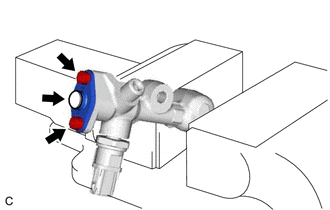
Secure the fuel delivery pipe sub-assembly in a vise between aluminum plates.
Note
Do not overtighten the vise.
-
Using a 5 mm hexagon socket wrench, remove the 2 bolts, gasket and fuel pipe support sub-assembly from the fuel delivery pipe sub-assembly.
-
Remove the dust cap sub-assembly from the fuel pipe support sub-assembly.
-
Remove the O-ring, No. 1 fuel injector back-up ring, No. 2 fuel injector back-up ring and No. 3 fuel injector back-up ring from the fuel pipe support sub-assembly.
-
Remove the fuel delivery pipe sub-assembly from the vise.
-