CAMSHAFT REMOVAL
CAUTION / NOTICE / HINT
The necessary procedures (adjustment, calibration, initialization, or registration) that must be performed after parts are removed and installed, or replaced during camshaft removal/installation are shown below.
| Replaced Part or Performed Procedure | Necessary Procedure | Effect/Inoperative Function when Necessary Procedure not Performed | Link | |
|---|---|---|---|---|
| Disconnect cable from negative battery terminal | Memorize steering angle neutral point | LKA/LDA System | ||
| Pre-crash safety system | ||||
| Lighting system (EXT)
|
||||
| Adaptive high beam system | ||||
| Parking Assist Monitor System (w/ Parallel Parking Assist Function) | ||||
| Parking Assist Monitor System (w/o Parallel Parking Assist Function) | ||||
| Panoramic view monitor system | ||||
| Initialize back door lock | Power door lock control system | |||
| Reset back door close position | Power back door system | |||
| Replacement of ECM | Perform Vehicle Identification Number (VIN) or frame number registration |
|
for 2GR-FKS (w/ Canister Pump Module): for 2GR-FKS (w/o Canister Pump Module) |
|
| ECU Communication ID Registration (Immobiliser system) | Engine start function | See Service Bulletin for the registration method. | ||
| Perform code registration (Immobiliser system) |
|
|||
w/ Canister Pump Module |
Inspection After Repair |
|
||
w/o Canister Pump Module |
Inspection After Repair |
|
||
| Replacement of automatic transaxle assembly | Perform the following procedures in the order shown:
|
|
for U881E Initialization: for U881E Registration: for U881F Initialization: for U881F Registration: |
|
| Replacement of ECM (If possible, read the transaxle compensation code from the previous ECM) |
Possible to read transaxle compensation code | Perform the following procedures in the order shown:
|
||
| Impossible to read transaxle compensation code | Perform the following procedures in the order shown:
|
|||
| Front wheel alignment adjustment |
|
|
||
| Suspension, tires, etc. (The vehicle height changes because of suspension or tire replacement) |
Rear television camera assembly optical axis (Back camera position setting) | Parking assist monitor system (w/ Parallel Parking Assist Function) | for Initialization: for Calibration: |
|
| Parking assist monitor system (w/o Parallel Parking Assist Function) | for Initialization: for Calibration: |
|||
|
Panoramic view monitor system | for Initialization: for Calibration: |
||
| Initialize headlight ECU sub-assembly LH |
|
|||
PROCEDURE
-
INSTALL ENGINE ASSEMBLY TO ENGINE STAND
-
REMOVE ENGINE HANGERS
-
REMOVE IGNITION COIL ASSEMBLY
-
REMOVE VACUUM PUMP ASSEMBLY
-
REMOVE ENGINE OIL LEVEL DIPSTICK GUIDE
-
REMOVE WIRE HARNESS CLAMP BRACKET
-
REMOVE RADIATOR PIPE CLAMP
-
REMOVE STUD BOLT
-
REMOVE CAMSHAFT TIMING OIL CONTROL SOLENOID ASSEMBLY (for Intake Side of Bank 1)
-
REMOVE CAMSHAFT TIMING OIL CONTROL SOLENOID ASSEMBLY (for Exhaust Side of Bank 1)
-
REMOVE CAMSHAFT TIMING OIL CONTROL SOLENOID ASSEMBLY (for Exhaust Side of Bank 2)
-
REMOVE CAMSHAFT TIMING OIL CONTROL SOLENOID ASSEMBLY (for Intake Side of Bank 2)
-
REMOVE VVT SENSOR (for Intake Side of Bank 1)
-
REMOVE VVT SENSOR (for Exhaust Side of Bank 1)
-
REMOVE VVT SENSOR (for Intake Side of Bank 2)
-
REMOVE VVT SENSOR (for Exhaust Side of Bank 2)
-
REMOVE CYLINDER HEAD COVER SUB-ASSEMBLY
-
REMOVE CYLINDER HEAD COVER SUB-ASSEMBLY LH
-
REMOVE SPARK PLUG TUBE GASKET
-
REMOVE TIMING CHAIN COVER PLATE
-
SET NO. 1 CYLINDER TO TDC (COMPRESSION)
-
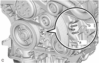
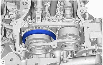
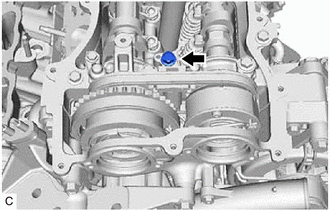
*a Timing Mark (Cutout) *b "0" Timing Mark Turn the crankshaft clockwise to align the timing mark (cutout) on the crankshaft pulley with the "0" timing mark on the timing chain cover assembly.
-
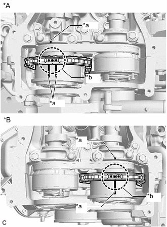
*A for Bank 2 *B for Bank 1 *a Timing Mark *b Paint Mark Check that the timing marks of the camshaft timing gear assemblies are aligned with the timing marks of the camshaft bearing caps as shown in the illustration.
Tech Tips
If the marks are not aligned, turn the crankshaft again to align the marks.
-
Place paint marks on the timing marks and sprockets of each camshaft timing gear assembly and on the links of the chain sub-assembly.
Tech Tips
Be sure to place the paint marks on 2 links of the chain sub-assembly and on the sprockets of the camshaft timing gear assemblies at the locations of the timing marks of the camshaft timing gear assemblies.
-
-
REMOVE NO. 1 CHAIN TENSIONER ASSEMBLY
-
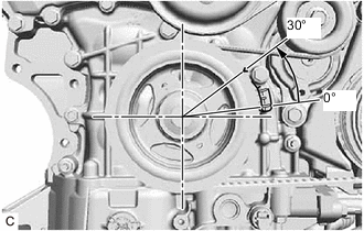
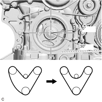
Turn the crankshaft approximately 30° counterclockwise so that there is some slack in the chain sub-assembly.
Tech Tips
This prevents the valves and pistons from interfering with each other.
-
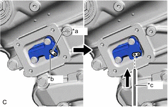
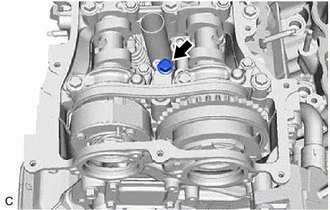
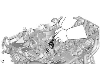
*a Lever Hole *b Tensioner Hole *c Pin Align the hole in the lever of the No. 1 chain tensioner assembly with the hole in the tensioner body as shown in the illustration, and then insert a pin with a diameter of 1.0 mm (0.0394 in.) into the hole.
Note
Check that the pin is locked.
-
*a Timing Mark (Cutout) *b "0" Timing Mark Turn the crankshaft clockwise to align the timing mark (cutout) on the crankshaft pulley with the "0" timing mark on the timing chain cover assembly.
-
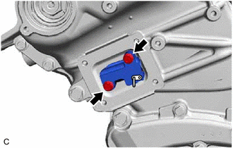
Remove the 2 bolts and No. 1 chain tensioner assembly from the cylinder head sub-assembly.
Note
Do not drop the No. 1 chain tensioner assembly or bolts into the timing chain cover assembly.
-
-
DISCONNECT CHAIN SUB-ASSEMBLY (for Bank 1)
-
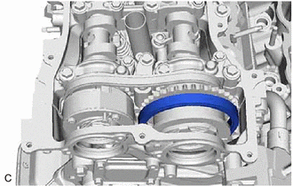
Turn the crankshaft clockwise until it is in the position shown in the illustration so that there is some slack in the chain sub-assembly between the banks.
CAUTION:
As the camshafts turn suddenly, do not touch the camshafts or camshaft timing gears.
Tech Tips
When turning the crankshaft, engine oil may spray out of the oil holes.
-
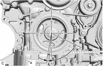
*a 5 to 10° Turn the crankshaft clockwise until it is in the position shown in the illustration so that the chain sub-assembly can be removed easily.
Tech Tips
When turning the crankshaft, engine oil may spray out of the oil holes.
-
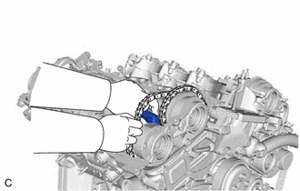
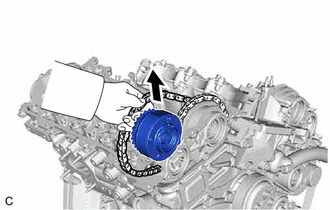
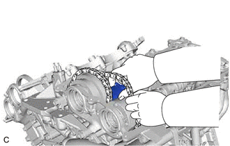
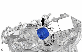
Remove the chain sub-assembly from the sprocket of the camshaft timing gear assembly and set it on the camshaft timing gear assembly.
CAUTION:
As the camshaft may turn suddenly and pinch your fingers when the chain sub-assembly is removed, pinch the chain sub-assembly and lift it upward to remove it from the sprocket.
-
-
SEPARATE NO. 2 CHAIN TENSIONER ASSEMBLY
-
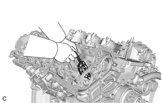
Remove the bolt of the No. 2 chain tensioner assembly.
-
-
REMOVE CAMSHAFT TIMING GEAR BOLT (for Intake Side of Bank 1)
-
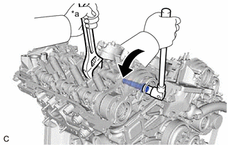
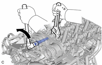
*a Hold 
Turn Hold the hexagonal portion of the camshaft with a wrench and remove the camshaft timing gear bolt from the camshaft timing gear assembly.
Note
-
Be careful not to damage the camshaft, camshaft housing sub-assembly or spark plug tube with the wrench.
-
If the camshaft timing gear bolt has been struck or dropped, replace it.
-
-
-
REMOVE CAMSHAFT TIMING GEAR BOLT (for Exhaust Side of Bank 1)
-
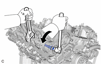
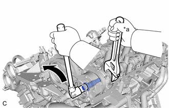
*a Hold Turn Hold the hexagonal portion of the No. 2 camshaft with a wrench and remove the camshaft timing gear bolt from the camshaft timing exhaust gear assembly.
Note
-
Be careful not to damage the camshaft, camshaft housing sub-assembly or spark plug tube with the wrench.
-
If the camshaft timing gear bolt has been struck or dropped, replace it.
-
-
-
REMOVE CAMSHAFT BEARING CAP (for Bank 1)
-
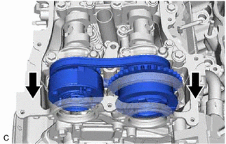
Slide the camshaft timing gear assembly and camshaft timing exhaust gear assembly as shown in the illustration.
-
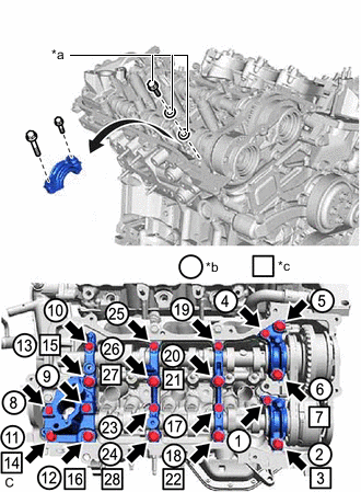
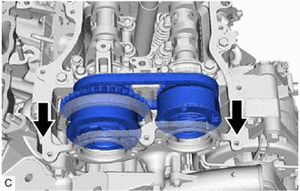
*a Replacement Bolt and Washer *b Part Removal *c Replacement Bolt and Washer Installation Remove the bolts and camshaft bearing caps in the order shown in the illustration. Immediately after removing a camshaft bearing cap, install replacement bolts and washers in the order shown in the illustration.
- Torque:
- 10 N*m { 102 kgf*cm, 7 ft.*lbf }
Note
-
Do not install the camshaft bearing caps when installing replacement bolts and washers.
-
Be sure to follow the numerical order when performing this procedure.
-
Do not allow replacement bolts or washers to contact the camshaft.
-
Do not drop replacement bolts or washers into the cylinder head sub-assembly.
Tech Tips
-
Arrange the removed parts so that they can be reinstalled in their original locations.
-
Part number for replacement bolts: 91551-F0850 (9 bolts)
-
Part number for replacement washers: 90201-12028 (18 washers)
-
-
REMOVE NO. 2 CAMSHAFT
-
While lifting up the camshaft timing exhaust gear assembly, remove the No. 2 chain tensioner assembly.
-
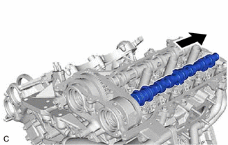
Lift up the rear of the No. 2 camshaft so that it is at an angle.
-
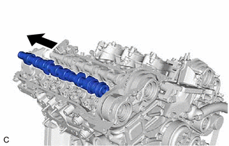
Pull the No. 2 camshaft as shown in the illustration to remove it from the camshaft timing exhaust gear assembly.
-
-
REMOVE CAMSHAFT
-
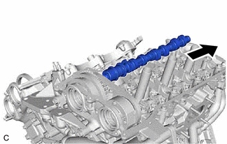
Lift up the rear of the camshaft so that it is at an angle.
-
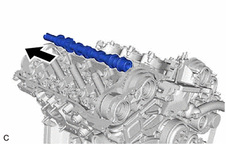
Pull the camshaft as shown in the illustration to remove it from the camshaft timing gear assembly.
-
-
REMOVE CAMSHAFT TIMING EXHAUST GEAR ASSEMBLY (for Bank 1)
-
Remove the camshaft timing exhaust gear assembly.
-
-
REMOVE CAMSHAFT TIMING GEAR ASSEMBLY (for Bank 1)
-
Remove the camshaft timing gear assembly and No. 2 chain sub-assembly.
Note
Do not drop the chain sub-assembly into the gap between the engine and timing chain cover assembly.
-
Suspend the chain sub-assembly with a string or equivalent.
-
-
DISCONNECT CHAIN SUB-ASSEMBLY (for Bank 2)
-
*a Timing Mark (Cutout) *b "0" Timing Mark Turn the crankshaft counterclockwise to align the timing mark (cutout) on the crankshaft pulley with the "0" timing mark on the timing chain cover assembly.
-
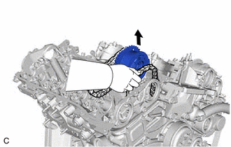
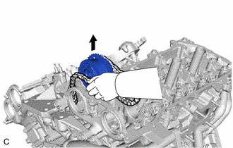
Remove the chain sub-assembly from the sprocket of the camshaft timing gear assembly and set it on the camshaft timing gear assembly.
CAUTION:
As the camshaft may turn suddenly and pinch your fingers when the chain sub-assembly is removed, pinch the chain sub-assembly and lift it upward to remove it from the sprocket.
-
-
SEPARATE NO. 3 CHAIN TENSIONER ASSEMBLY
-
Remove the bolt of the No. 3 chain tensioner assembly.
-
-
REMOVE CAMSHAFT TIMING GEAR BOLT (for Intake Side of Bank 2)
-
*a Hold Turn Hold the hexagonal portion of the No. 3 camshaft sub-assembly with a wrench and remove the camshaft timing gear bolt from the camshaft timing gear assembly.
Note
-
Be careful not to damage the No. 3 camshaft sub-assembly, camshaft housing sub-assembly LH or spark plug tube with the wrench.
-
If the camshaft timing gear bolt has been struck or dropped, replace it.
-
-
-
REMOVE CAMSHAFT TIMING GEAR BOLT (for Exhaust Side of Bank 2)
-
*a Hold Turn Hold the hexagonal portion of the No. 4 camshaft sub-assembly with a wrench and remove the camshaft timing gear bolt from the camshaft timing exhaust gear assembly.
Note
-
Be careful not to damage the No. 4 camshaft sub-assembly, camshaft housing sub-assembly LH or spark plug tube with the wrench.
-
If the camshaft timing gear bolt has been struck or dropped, replace it.
-
-
-
REMOVE CAMSHAFT BEARING CAP (for Bank 2)
-
Slide the camshaft timing gear assembly and camshaft timing exhaust gear assembly as shown in the illustration.
-
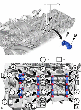
*a Replacement Bolt and Washer *b Part Removal *c Replacement Bolt and Washer Installation Remove the bolts and camshaft bearing caps in the order shown in the illustration. Immediately after removing a camshaft bearing cap, install replacement bolts and washers in the order shown in the illustration.
- Torque:
- 10 N*m { 102 kgf*cm, 7 ft.*lbf }
Note
-
Do not install the camshaft bearing caps when installing replacement bolts and washers.
-
Be sure to follow the numerical order when performing this procedure.
-
Do not allow replacement bolts or washers to contact the camshaft.
-
Do not drop replacement bolts or washers into the cylinder head LH.
Tech Tips
-
Arrange the removed parts so that they can be reinstalled in their original locations.
-
Part number for replacement bolts: 91551-F0850 (8 bolts)
-
Part number for replacement washers: 90201-12028 (16 washers)
-
-
REMOVE NO. 4 CAMSHAFT SUB-ASSEMBLY
-
While lifting up the camshaft timing exhaust gear assembly, remove the No. 3 chain tensioner assembly.
-
Lift up the rear of the No. 4 camshaft sub-assembly so that it is at an angle.
-
Pull the No. 4 camshaft sub-assembly as shown in the illustration to remove it from the camshaft timing exhaust gear assembly.
-
-
REMOVE NO. 3 CAMSHAFT SUB-ASSEMBLY
-
Lift up the rear of the No. 3 camshaft sub-assembly so that it is at an angle.
-
Pull the No. 3 camshaft sub-assembly as shown in the illustration to remove it from the camshaft timing gear assembly.
-
-
REMOVE CAMSHAFT TIMING EXHAUST GEAR ASSEMBLY (for Bank 2)
-
Remove the camshaft timing exhaust gear assembly.
-
-
REMOVE CAMSHAFT TIMING GEAR ASSEMBLY (for Bank 2)
-
Remove the camshaft timing gear assembly and No. 2 chain sub-assembly.
Note
Do not drop the chain sub-assembly into the gap between the engine and timing chain cover assembly.
-
Suspend the chain sub-assembly with a string or equivalent.
-