REAR CRANKSHAFT OIL SEAL REMOVAL

CAUTION / NOTICE / HINT
The necessary procedures (adjustment, calibration, initialization, or registration) that must be performed after parts are removed and installed, or replaced during rear crankshaft oil seal removal/installation are shown below.
| Replaced Part or Performed Procedure | Necessary Procedure | Effect/Inoperative Function when Necessary Procedure not Performed | Link | |
|---|---|---|---|---|
| Disconnect cable from negative battery terminal | Memorize steering angle neutral point | LKA/LDA System | ||
| Pre-crash safety system | ||||
| Lighting system (EXT)
|
||||
| Adaptive high beam system | ||||
| Parking Assist Monitor System (w/ Parallel Parking Assist Function) | ||||
| Parking Assist Monitor System (w/o Parallel Parking Assist Function) | ||||
| Panoramic view monitor system | ||||
| Initialize back door lock | Power door lock control system | |||
| Reset back door close position | Power back door system | |||
| Replacement of ECM | Perform Vehicle Identification Number (VIN) or frame number registration |
|
for 2GR-FKS (w/ Canister Pump Module): for 2GR-FKS (w/o Canister Pump Module) |
|
| ECU Communication ID Registration (Immobiliser system) | Engine start function | See Service Bulletin for the registration method. | ||
| Perform code registration (Immobiliser system) |
|
|||
w/ Canister Pump Module |
Inspection After Repair |
|
||
w/o Canister Pump Module |
Inspection After Repair |
|
||
| Replacement of automatic transaxle assembly | Perform the following procedures in the order shown:
|
|
for U881E Initialization: for U881E Registration: for U881F Initialization: for U881F Registration: |
|
| Replacement of ECM (If possible, read the transaxle compensation code from the previous ECM) |
Possible to read transaxle compensation code | Perform the following procedures in the order shown:
|
||
| Impossible to read transaxle compensation code | Perform the following procedures in the order shown:
|
|||
| Front wheel alignment adjustment |
|
|
||
| Suspension, tires, etc. (The vehicle height changes because of suspension or tire replacement) |
Rear television camera assembly optical axis (Back camera position setting) | Parking assist monitor system (w/ Parallel Parking Assist Function) | for Initialization: for Calibration: |
|
| Parking assist monitor system (w/o Parallel Parking Assist Function) | for Initialization: for Calibration: |
|||
|
Panoramic view monitor system | for Initialization: for Calibration: |
||
| Initialize headlight ECU sub-assembly LH |
|
|||
PROCEDURE
-
REMOVE AUTOMATIC TRANSAXLE ASSEMBLY
for U881E: Click here
for U881F: Click here
-
REMOVE DRIVE PLATE AND RING GEAR SUB-ASSEMBLY
-
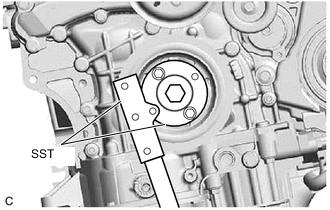
Using SST, hold the crankshaft pulley.
- SST
- 09213-70011 ( 09213-70020 )
- 09330-00021
-
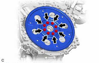
Remove the 8 bolts, the rear drive plate spacer, the drive plate and ring gear sub-assembly and the No. 1 crankshaft position sensor plate.
-
-
REMOVE REAR ENGINE OIL SEAL
-
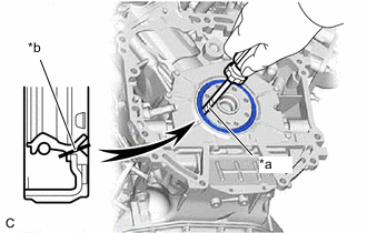
*a Protective Tape *b Cut Position Using a knife, cut through the lip of the rear engine oil seal.
-
Using a screwdriver with its tip wrapped with protective tape, pry out the rear engine oil seal.
Note
Be careful not to damage the crankshaft.
-