CYLINDER HEAD GASKET REMOVAL
CAUTION / NOTICE / HINT
The necessary procedures (adjustment, calibration, initialization, or registration) that must be performed after parts are removed and installed, or replaced during cylinder head gasket removal/installation are shown below.
| Replaced Part or Performed Procedure | Necessary Procedure | Effect/Inoperative Function when Necessary Procedure not Performed | Link | |
|---|---|---|---|---|
| Disconnect cable from negative battery terminal | Memorize steering angle neutral point | LKA/LDA System | ||
| Intelligent clearance sonar system*2 | ||||
| Pre-crash safety system | ||||
| Lighting system (EXT)
|
||||
| Adaptive high beam system | ||||
| Parking Assist Monitor System (w/ Parallel Parking Assist Function) | ||||
| Parking Assist Monitor System (w/o Parallel Parking Assist Function) | ||||
| Panoramic view monitor system | ||||
| Initialize back door lock | Power door lock control system | |||
| Reset back door close position | Power back door system | |||
| Replacement of ECM | Perform Vehicle Identification Number (VIN) or frame number registration |
|
for 2GR-FKS (w/ Canister Pump Module): for 2GR-FKS (w/o Canister Pump Module) |
|
| ECU Communication ID Registration (Immobiliser system) | Engine start function | See Service Bulletin for the registration method. | ||
| Perform code registration (Immobiliser system) |
|
|||
| Replacement of ECM (If possible, read the transaxle compensation code from the previous ECM) |
Possible to read transaxle compensation code | Perform the following procedures in the order shown:
|
|
Click here for Initialization (U881E) Click here for Registration (U881E) Click here for Initialization (U881F) Click here for Registration (U881F) |
| Impossible to read transaxle compensation code | Perform the following procedures in the order shown:
|
|||
w/ Canister Pump Module |
Inspection After Repair |
|
||
w/o Canister Pump Module |
Inspection After Repair |
|
||
| Replacement of automatic transaxle assembly | Perform the following procedures in the order shown:
|
|
for U881E Initialization: for U881E Registration: for U881F Initialization: for U881F Registration: |
|
| Front wheel alignment adjustment |
|
|
||
| Suspension, tires, etc. (The vehicle height changes because of suspension or tire replacement) |
|
|
||
| Rear television camera assembly optical axis (Back camera position setting) | Parking assist monitor system (w/ Parallel Parking Assist Function) | for Initialization: for Calibration: |
||
| Parking assist monitor system (w/o Parallel Parking Assist Function) | for Initialization: for Calibration: |
|||
|
Panoramic view monitor system | for Initialization: for Calibration: |
||
| Initialize headlight ECU sub-assembly LH |
|
|||
*2: When performing learning using the GTS.
Click here Click here
PROCEDURE
-
INSTALL ENGINE ASSEMBLY TO ENGINE STAND
-
REMOVE ENGINE HANGERS
-
REMOVE KNOCK CONTROL SENSOR
-
REMOVE IGNITION COIL ASSEMBLY
-
REMOVE VACUUM PUMP ASSEMBLY
-
REMOVE V-RIBBED BELT
-
REMOVE GENERATOR ASSEMBLY
-
REMOVE COMPRESSOR AND MAGNETIC CLUTCH
-
REMOVE NO. 2 IDLER PULLEY SUB-ASSEMBLY
-
REMOVE V-RIBBED BELT TENSIONER ASSEMBLY
-
REMOVE WATER PUMP PULLEY
-
REMOVE ENGINE OIL LEVEL DIPSTICK GUIDE
-
REMOVE NO. 5 CYLINDER BLOCK INSULATOR (w/ Oil Cooler)
-
REMOVE WIRE HARNESS CLAMP BRACKET
-
REMOVE RADIATOR PIPE CLAMP
-
REMOVE CRANKSHAFT PULLEY
-
REMOVE FRONT NO. 1 ENGINE MOUNTING BRACKET LH
-
DISCONNECT WATER BY-PASS HOSE
-
REMOVE WATER INLET WITH THERMOSTAT SUB-ASSEMBLY
-
REMOVE CAMSHAFT TIMING OIL CONTROL SOLENOID ASSEMBLY (for Intake Side of Bank 1)
-
REMOVE CAMSHAFT TIMING OIL CONTROL SOLENOID ASSEMBLY (for Exhaust Side of Bank 1)
-
REMOVE CAMSHAFT TIMING OIL CONTROL SOLENOID ASSEMBLY (for Exhaust Side of Bank 2)
-
REMOVE CAMSHAFT TIMING OIL CONTROL SOLENOID ASSEMBLY (for Intake Side of Bank 2)
-
REMOVE VVT SENSOR (for Intake Side of Bank 1)
-
REMOVE VVT SENSOR (for Exhaust Side of Bank 1)
-
REMOVE VVT SENSOR (for Intake Side of Bank 2)
-
REMOVE VVT SENSOR (for Exhaust Side of Bank 2)
-
REMOVE CRANKSHAFT POSITION SENSOR PROTECTOR
-
REMOVE SENSOR WIRE
-
REMOVE CYLINDER HEAD COVER SUB-ASSEMBLY
-
REMOVE CYLINDER HEAD COVER SUB-ASSEMBLY LH
-
REMOVE SPARK PLUG TUBE GASKET
-
REMOVE OIL COOLER ASSEMBLY (w/ Oil Cooler)
-
REMOVE OIL COOLER PIPE (w/ Oil Cooler)
-
REMOVE NO. 2 OIL PAN SUB-ASSEMBLY
-
REMOVE OIL STRAINER SUB-ASSEMBLY
-
REMOVE OIL PAN SUB-ASSEMBLY
-
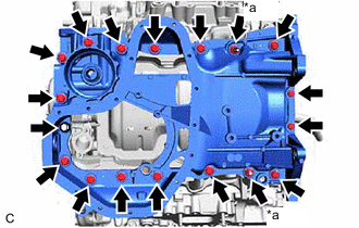
*a Nut Remove the 16 bolts and 2 nuts from the oil pan sub-assembly.
Note
Make sure to clean the bolts and stud bolts and check the threads for cracks or other damage.
-
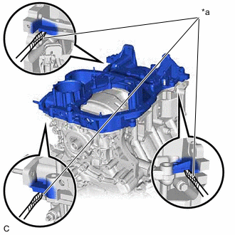
*a Protective Tape Remove the oil pan sub-assembly by prying between the oil pan sub-assembly and timing chain cover assembly or cylinder block sub-assembly with a screwdriver wrapped with protective tape.
Note
Be careful not to damage the contact surfaces of the cylinder block sub-assembly, timing chain cover assembly and oil pan sub-assembly.
-
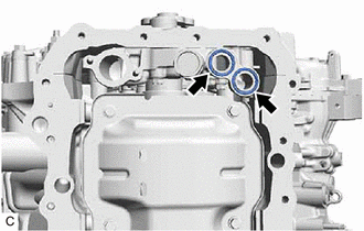
Remove the 2 oil pan gaskets from the timing chain cover assembly.
-
-
REMOVE TIMING CHAIN COVER ASSEMBLY
-
REMOVE TIMING CHAIN CASE OIL SEAL
-
SET NO. 1 CYLINDER TO TDC (COMPRESSION)
-
REMOVE NO. 1 CHAIN TENSIONER ASSEMBLY
-
REMOVE CHAIN TENSIONER SLIPPER
-
REMOVE CHAIN SUB-ASSEMBLY
-
REMOVE CAMSHAFT TIMING GEAR ASSEMBLY, CAMSHAFT TIMING EXHAUST GEAR ASSEMBLY AND NO. 2 CHAIN SUB-ASSEMBLY (for Bank 1)
-
REMOVE NO. 2 CHAIN TENSIONER ASSEMBLY
-
REMOVE CAMSHAFT BEARING CAP (for Bank 1)
-
REMOVE CAMSHAFT
-
REMOVE NO. 2 CAMSHAFT
-
REMOVE CAMSHAFT HOUSING SUB-ASSEMBLY
-
REMOVE CAMSHAFT TIMING GEAR ASSEMBLY, CAMSHAFT TIMING EXHAUST GEAR ASSEMBLY AND NO. 2 CHAIN SUB-ASSEMBLY (for Bank 2)
-
REMOVE NO. 3 CHAIN TENSIONER ASSEMBLY
-
REMOVE CAMSHAFT BEARING CAP (for Bank 2)
-
REMOVE NO. 3 CAMSHAFT SUB-ASSEMBLY
-
REMOVE NO. 4 CAMSHAFT SUB-ASSEMBLY
-
REMOVE CAMSHAFT HOUSING SUB-ASSEMBLY LH
-
REMOVE SENSOR WIRE
-
REMOVE NO. 1 CHAIN VIBRATION DAMPER
-
REMOVE NO. 2 CHAIN VIBRATION DAMPER
-
REMOVE NO. 1 VALVE ROCKER ARM SUB-ASSEMBLY
-
REMOVE VALVE LASH ADJUSTER ASSEMBLY
-
REMOVE VALVE STEM CAP
-
REMOVE WATER OUTLET
-
REMOVE CYLINDER HEAD SUB-ASSEMBLY
-
REMOVE CYLINDER HEAD GASKET
-
Remove the cylinder head gasket from the cylinder block sub-assembly.
-
-
REMOVE CYLINDER HEAD LH
-
REMOVE NO. 2 CYLINDER HEAD GASKET
-
Remove the No. 2 cylinder head gasket from the cylinder block sub-assembly.
-
-
INSPECT CYLINDER HEAD SET BOLT