REAR SUSPENSION MEMBER(for AWD) INSTALLATION

PROCEDURE
-
INSTALL HOLE PLUG
-
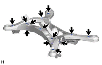
Install the 13 hole plugs to the rear suspension member sub-assembly as shown in the illustration.
Tech Tips
The upper and lower hole plug shapes are different.
-
-
INSTALL REAR SUSPENSION MEMBER FRONT BODY MOUNTING CUSHION (for LH Side)
-
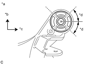
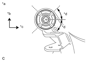
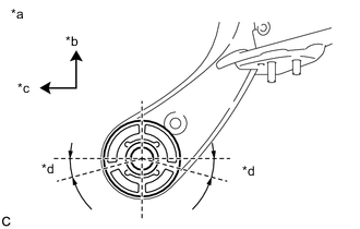
*a View from Underneath *b Front of the Vehicle *c Left Side of the Vehicle *d 45° Confirm the installation direction and temporarily install a new rear suspension member front body mounting cushion.
-
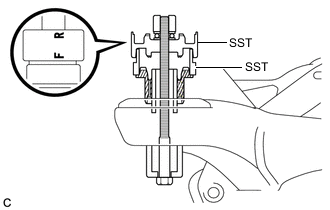
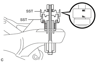
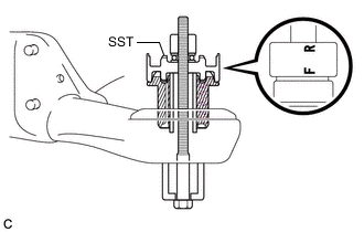
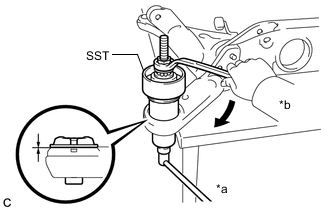
Install SST as shown in the illustration.
- SST
- 09527-17011
- 09830-10010 ( 09830-01010, 09830-01020, 09830-01030, 09830-01060 )
Note
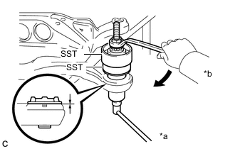
Apply grease to the threads and tip of the SST center bolt before use.
Tech Tips
Use SST with the "F" mark facing the rear suspension member front body mounting cushion.
-
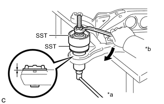
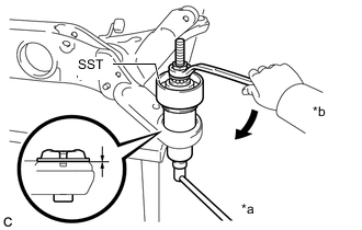
*a Hold *b Turn Using SST, install the rear suspension member front body mounting cushion until there is no clearance between the rear suspension member sub-assembly and rear suspension member front body mounting cushion.
- SST
- 09527-17011
- 09830-10010 ( 09830-01010, 09830-01020, 09830-01030, 09830-01060 )
Note
If the rear suspension member sub-assembly is scratched, apply paint to the scratched areas of the rear suspension member sub-assembly.
-
Remove SST from the rear suspension member sub-assembly.
-
-
INSTALL REAR SUSPENSION MEMBER FRONT BODY MOUNTING CUSHION (for RH Side)
-
*a View from Underneath *b Front of the Vehicle *c Left Side of the Vehicle *d 45° Confirm the installation direction and temporarily install a new rear suspension member front body mounting cushion.
-
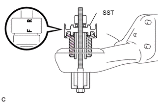
Install SST as shown in the illustration.
- SST
- 09527-17011
- 09830-10010 ( 09830-01010, 09830-01020, 09830-01030, 09830-01060 )
Note
Apply grease to the threads and tip of the SST center bolt before use.
Tech Tips
Use SST with the "F" mark facing the rear suspension member front body mounting cushion.
-
*a Hold *b Turn Using SST, install the rear suspension member front body mounting cushion until there is no clearance between the rear suspension member sub-assembly and rear suspension member front body mounting cushion.
- SST
- 09527-17011
- 09830-10010 ( 09830-01010, 09830-01020, 09830-01030, 09830-01060 )
Note
If the rear suspension member sub-assembly is scratched, apply paint to the scratched areas of the rear suspension member sub-assembly.
-
Remove SST from the rear suspension member sub-assembly.
-
-
INSTALL REAR SUSPENSION MEMBER REAR BODY MOUNT CUSHION LH
-
*a View from Underneath *b Front of the Vehicle *c Left Side of the Vehicle Confirm the installation direction and temporarily install a new rear suspension member rear body mount cushion LH.
-
Install SST as shown in the illustration.
- SST
- 09830-10010 ( 09830-01010, 09830-01020, 09830-01030, 09830-01060 )
Note
Apply grease to the threads and tip of the SST center bolt before use.
Tech Tips
Use SST with the "F" mark facing the rear suspension member rear body mount cushion LH.
-
*a Hold *b Turn Using SST, install the rear suspension member rear body mount cushion LH until there is no clearance between the rear suspension member sub-assembly and rear suspension member rear body mount cushion LH.
- SST
- 09830-10010 ( 09830-01010, 09830-01020, 09830-01030, 09830-01060 )
Note
If the rear suspension member sub-assembly is scratched, apply paint to the scratched areas of the rear suspension member sub-assembly.
-
Remove SST from the rear suspension member sub-assembly.
-
-
INSTALL REAR SUSPENSION MEMBER REAR BODY MOUNT CUSHION RH
-
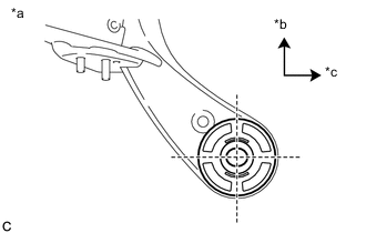
*a View from Underneath *b Front of the Vehicle *c Right Side of the Vehicle *d 15° Confirm the installation direction and temporarily install a new rear suspension member rear body mount cushion RH.
-
Install SST as shown in the illustration.
- SST
- 09830-10010 ( 09830-01010, 09830-01020, 09830-01030, 09830-01060 )
Note
Apply grease to the threads and tip of the SST center bolt before use.
Tech Tips
Use SST with the "F" mark facing the rear suspension member rear body mount cushion RH.
-
*a Hold *b Turn Using SST, install the rear suspension member rear body mount cushion RH until there is no clearance between the rear suspension member sub-assembly and rear suspension member rear body mount cushion RH.
- SST
- 09830-10010 ( 09830-01010, 09830-01020, 09830-01030, 09830-01060 )
Note
If the rear suspension member sub-assembly is scratched, apply paint to the scratched areas of the rear suspension member sub-assembly.
-
Remove SST from the rear suspension member sub-assembly.
-
-
INSTALL REAR NO. 2 DIFFERENTIAL MOUNT CUSHION
-
INSTALL REAR UPPER CONTROL ARM ASSEMBLY LH
-
INSTALL REAR UPPER CONTROL ARM ASSEMBLY RH
Tech Tips
Perform the same procedure as for the LH side.
-
INSTALL REAR SUSPENSION MEMBER UPPER STOPPER
-
Install the 2 rear suspension member upper stoppers to the rear suspension member sub-assembly.
-
-
INSTALL REAR SUSPENSION MEMBER REAR UPPER STOPPER
-
Install the 2 rear suspension member rear upper stoppers to the rear suspension member sub-assembly.
-
-
INSTALL REAR SUSPENSION MEMBER SUB-ASSEMBLY
-
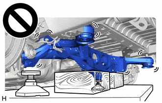
Using an engine lifter, 2 attachments and 2 wooden blocks or equivalent tools, support the rear suspension member sub-assembly as shown in the illustration.
CAUTION:
-
The rear suspension member sub-assembly is a very heavy component. Make sure that it is supported securely.
-
If the rear suspension member sub-assembly is not securely supported, it may drop, resulting in serious injury.
Note
-
Use attachments and wooden blocks to keep the rear suspension member sub-assembly level.
-
Keep supporting the rear suspension member sub-assembly until the installation has been completed.
-
-
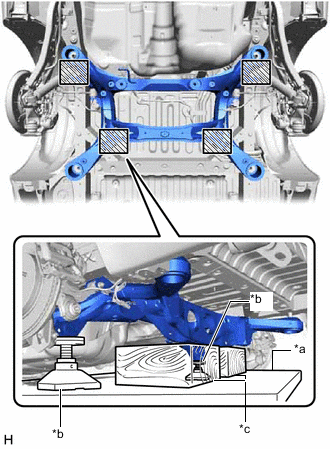
*a Engine Lifter *b Attachment *c Wooden Block 
Attachment and Wooden Block Placement Location Raise the rear suspension member sub-assembly until there is no clearance between the rear suspension member sub-assembly and vehicle body.
-
Install the rear suspension member sub-assembly with the 2 rear lower suspension braces, rear lower suspension member stopper LH and rear lower suspension member stopper RH, with the 4 bolts and 2 nuts.
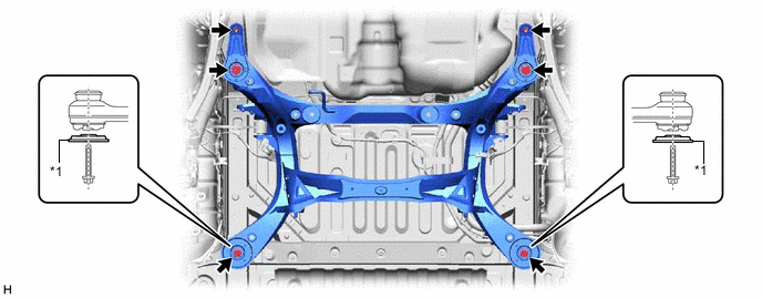
*1 Rear Lower Suspension Brace - - - Torque:
- Bolt
- 158 N*m { 1611 kgf*cm, 117 ft.*lbf }
- Nut
- 32 N*m { 326 kgf*cm, 24 ft.*lbf }
Note
Be sure to install the rear suspension member sub-assembly with the rear lower suspension braces facing in the correct direction as shown in the illustration.
-
Lower the engine lifter.
-
-
INSTALL NO. 3 FLOOR WIRE
-
Install the No. 3 floor wire to the rear suspension member sub-assembly with the bolt and 3 clamps.
- Torque:
- 7.5 N*m { 76 kgf*cm, 66 in.*lbf }
Note
Do not twist the No. 3 floor wire when installing it.
-
-
INSTALL REAR DIFFERENTIAL CARRIER ASSEMBLY
-
INSTALL REAR DRIVE SHAFT SNAP RING (for LH Side)
-
INSTALL REAR DRIVE SHAFT SNAP RING (for RH Side)
Tech Tips
Perform the same procedure as for the LH side.
-
INSTALL REAR DRIVE SHAFT ASSEMBLY LH
-
INSTALL REAR DRIVE SHAFT ASSEMBLY RH
Tech Tips
Perform the same procedure as for the LH side.
-
CONNECT REAR UPPER CONTROL ARM ASSEMBLY LH
-
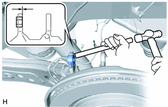
Using a brass bar and a hammer, push out the bushing until it is positioned as shown in the illustration.
Tech Tips
Pushing out the bushing makes it easier to connect the rear upper control arm assembly LH.
-
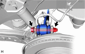
Connect the rear upper control arm assembly LH to the rear axle carrier sub-assembly LH with the bolt and nut.
- Torque:
- 145 N*m { 1479 kgf*cm, 107 ft.*lbf }
Note
-
Insert the bolt with the threaded end facing the rear of the vehicle.
-
Because the nut has its own stopper, do not turn the nut. Tighten the bolt with the nut secured.
-
-
CONNECT REAR UPPER CONTROL ARM ASSEMBLY RH
Tech Tips
Perform the same procedure as for the LH side.
-
TEMPORARILY INSTALL REAR NO. 1 SUSPENSION ARM ASSEMBLY LH
-
TEMPORARILY INSTALL REAR NO. 1 SUSPENSION ARM ASSEMBLY RH
Tech Tips
Perform the same procedure as for the LH side.
-
TEMPORARILY INSTALL REAR NO. 2 SUSPENSION ARM ASSEMBLY LH
-
TEMPORARILY INSTALL REAR NO. 2 SUSPENSION ARM ASSEMBLY RH
Tech Tips
Perform the same procedure as for the LH side.
-
INSTALL REAR LOWER COIL SPRING INSULATOR LH
-
INSTALL REAR LOWER COIL SPRING INSULATOR RH
Tech Tips
Perform the same procedure as for the LH side.
-
INSTALL REAR COIL SPRING LH
-
INSTALL REAR COIL SPRING RH
Tech Tips
Perform the same procedure as for the LH side.
-
INSTALL REAR STABILIZER BAR
-
INSTALL REAR STABILIZER LINK ASSEMBLY LH
-
INSTALL REAR STABILIZER LINK ASSEMBLY RH
Tech Tips
Perform the same procedure as for the LH side.
-
INSTALL REAR SPEED SENSOR LH (w/o AVS)
-
Install the rear speed sensor LH with the 2 bolts and nut.
- Torque:
- 8.5 N*m { 87 kgf*cm, 75 in.*lbf }
-
Connect the connector.
-
-
INSTALL REAR SPEED SENSOR RH (w/o AVS)
-
Install the rear speed sensor RH with the 2 bolts and nut.
- Torque:
- 8.5 N*m { 87 kgf*cm, 75 in.*lbf }
-
Connect the connector and engage the 2 clamps.
-
-
INSTALL REAR NO. 2 SKID CONTROL SENSOR WIRE LH (w/ AVS)
-
Install the rear No. 2 skid control sensor wire LH with the 2 bolts and 4 nuts.
- Torque:
- 8.5 N*m { 87 kgf*cm, 75 in.*lbf }
-
Connect the 3 connectors.
-
-
INSTALL REAR NO. 2 SKID CONTROL SENSOR WIRE RH (w/ AVS)
-
Install the rear No. 2 skid control sensor wire RH with the 2 bolts and 4 nuts.
- Torque:
- 8.5 N*m { 87 kgf*cm, 75 in.*lbf }
-
Connect the 3 connectors and engage the 3 clamps.
-
-
CONNECT REAR SPEED SENSOR LH
-
Install the rear speed sensor LH to the rear trailing arm assembly LH with the bolt.
- Torque:
- 8.5 N*m { 87 kgf*cm, 75 in.*lbf }
Note
Do not twist the rear speed sensor when installing it.
-
Connect the rear speed sensor LH to the rear axle carrier sub-assembly LH with the bolt.
- Torque:
- 8.5 N*m { 87 kgf*cm, 75 in.*lbf }
Note
Do not twist the rear speed sensor LH when installing it.
-
-
CONNECT REAR SPEED SENSOR RH
Tech Tips
Perform the same procedure as for the LH side.
-
CONNECT NO. 2 PARKING BRAKE WIRE ASSEMBLY
-
CONNECT NO. 1 PARKING BRAKE WIRE ASSEMBLY
Tech Tips
Perform the same procedure as for the LH side.
-
INSTALL REAR HEIGHT CONTROL SENSOR SUB-ASSEMBLY RH
-
INSTALL REAR AXLE SHAFT NUT LH
-
INSTALL REAR AXLE SHAFT NUT RH
Tech Tips
Perform the same procedure as for the LH side.
-
CONNECT REAR FLEXIBLE HOSE LH
-
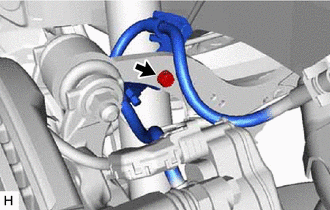
Connect the rear flexible hose LH to the rear upper control arm assembly LH with the bolt.
- Torque:
- 18.8 N*m { 192 kgf*cm, 14 ft.*lbf }
-
-
CONNECT REAR FLEXIBLE HOSE RH
Tech Tips
Perform the same procedure as for the LH side.
-
STABILIZE SUSPENSION
-
INSTALL REAR NO. 1 SUSPENSION ARM ASSEMBLY LH
-
INSTALL REAR NO. 1 SUSPENSION ARM ASSEMBLY RH
Tech Tips
Perform the same procedure as for the LH side.
-
INSTALL REAR SUSPENSION ARM COVER LH
-
INSTALL REAR SUSPENSION ARM COVER RH
Tech Tips
Perform the same procedure as for the LH side.
-
INSTALL PROPELLER WITH CENTER BEARING SHAFT ASSEMBLY
-
INSTALL TAIL EXHAUST PIPE ASSEMBLY
for 8AR-FTS: Click here
for 2GR-FKS: Click here
-
INSTALL REAR WHEEL
-
INSTALL REAR NO. 2 SUSPENSION ARM ASSEMBLY LH
-
INSTALL REAR NO. 2 SUSPENSION ARM ASSEMBLY RH
Tech Tips
Perform the same procedure as for the LH side.
-
ADD DIFFERENTIAL OIL
-
INSPECT FOR DIFFERENTIAL OIL LEAK
-
INSPECT FOR EXHAUST GAS LEAK
for 8AR-FTS: Click here
for 2GR-FKS: Click here
-
INSPECT AND ADJUST REAR WHEEL ALIGNMENT
-
CHECK FOR SPEED SENSOR SIGNAL
-
PERFORM INITIALIZATION
-
Intelligent clearance sonar system
-
LEXUS parking assist-sensor system (w/ Intelligent Clearance Sonar System)
Parking assist monitor system (w/ Parallel Parking Assist Function) for Initialization: Click here
for Calibration: Click here
Parking assist monitor system (w/o Parallel Parking Assist Function) for Initialization: Click here
for Calibration: Click here
Panoramic view monitor system for Initialization: Click here
for Calibration: Click here
-
Adaptive high beam system
-
Automatic headlight beam level control system
-