REAR SHOCK ABSORBER INSTALLATION
CAUTION / NOTICE / HINT
Tech Tips
-
Use the same procedure for the RH side and LH side.
-
The following procedure is for the LH side.
PROCEDURE
-
TEMPORARILY INSTALL REAR SHOCK ABSORBER ASSEMBLY (w/o AVS)
-
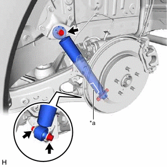
*a Protector Temporarily install the rear shock absorber assembly with the 2 bolts and nut.
Note
-
Ensure that the protector faces the front of the vehicle.
-
Insert the bolt with the threaded end facing the rear of the vehicle.
-
Because the nut has its own stopper, do not turn the nut. Tighten the bolt with the nut secured.
-
-
-
TEMPORARILY INSTALL REAR SHOCK ABSORBER ASSEMBLY (w/ AVS)
-
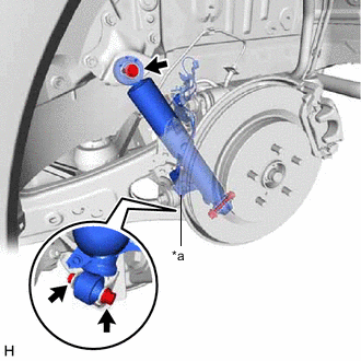
*a Protector Temporarily install the rear shock absorber assembly with the 2 bolts and nut.
Note
-
Ensure that the protector faces the front of the vehicle.
-
Insert the bolt with the threaded end facing the rear of the vehicle.
-
Because the nut has its own stopper, do not turn the nut. Tighten the bolt with the nut secured.
-
-
-
INSTALL REAR NO. 2 SKID CONTROL SENSOR WIRE LH (w/ AVS)
-
Install the rear No. 2 skid control sensor wire LH with the bolt and 4 nuts.
- Torque:
- 8.5 N*m { 87 kgf*cm, 75 in.*lbf }
-
Connect the 3 connectors.
-
-
INSTALL REAR NO. 2 SKID CONTROL SENSOR WIRE RH (w/ AVS)
-
Install the rear No. 2 skid control sensor wire RH with the bolt and 4 nuts.
- Torque:
- 8.5 N*m { 87 kgf*cm, 75 in.*lbf }
-
Connect the 3 connectors and engage the 3 clamps.
-
-
STABILIZE SUSPENSION
-
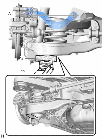
*a Wooden Block *b Jack 
Wooden Block Placement Location Using a jack and a wooden block, apply load to the suspension so that the rear upper control arm assembly is positioned as shown in the illustration.
Standard Length (A) 24.3 mm (0.957 in.) CAUTION:
Do not jack up the rear No. 2 suspension arm assembly too high as the vehicle may fall.
Note
-
When jacking up the rear No. 2 suspension arm assembly, be sure to jack it up slowly.
-
Make sure to perform this operation with the vehicle kept as low as possible.
-
-
-
INSTALL REAR SHOCK ABSORBER ASSEMBLY
-
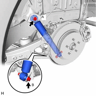
Install the rear shock absorber assembly with the bolt (A) and bolt (B).
- Torque:
- Bolt (A)
- 90 N*m { 918 kgf*cm, 66 ft.*lbf }
- Bolt (B)
- 92 N*m { 938 kgf*cm, 68 ft.*lbf }
Note
Because the nut has its own stopper, do not turn the nut. Tighten the bolt with the nut secured.
-
-
INSTALL REAR SUSPENSION ARM COVER
-
INSTALL REAR WHEEL
-
PERFORM INITIALIZATION
Parking assist monitor system (w/ Parallel Parking Assist Function) for Initialization: Click here
for Calibration: Click here
Parking assist monitor system (w/o Parallel Parking Assist Function) for Initialization: Click here
for Calibration: Click here
Panoramic view monitor system for Initialization: Click here
for Calibration: Click here
-
Adaptive high beam system
-
Automatic headlight beam level control system
-