AIR CONDITIONING UNIT REMOVAL
CAUTION / NOTICE / HINT
The necessary procedures (adjustment, calibration, initialization, or registration) that must be performed after parts are removed, installed, or replaced during the air conditioner unit assembly removal/installation are shown below.
| Replacement Part or Procedure | Necessary Procedure | Effect/Inoperative when not Performed | Link |
|---|---|---|---|
| Disconnect cable from negative battery terminal | Correct the steering angle neutral point | Parking assist monitor system | |
| LKA/LDA system | |||
| Pre-crash safety system | |||
| Adaptive high beam system | |||
| Reset power trunk lid | Power trunk lid system |
CAUTION / NOTICE / HINT
CAUTION:
Some of these service operations affect the SRS airbag system. Read the precautionary notices concerning the SRS airbag system before servicing.
Note
After turning the engine switch off, waiting time may be required before disconnecting the cable from the battery negative (-) terminal. Therefore, make sure to read the disconnecting the cable from the battery negative (-) terminal notices before proceeding with work.
Tech Tips
If the air conditioning radiator damper servo sub-assembly is to be removed and installed or replaced, make sure to set the temperature setting to MAX COLD before turning the engine switch off and disconnecting the cable from the negative (-) battery terminal.
PROCEDURE
-
REMOVE COOL AIR INTAKE DUCT SEAL
-
REMOVE V-BANK COVER SUB-ASSEMBLY
-
REMOVE AIR CLEANER CAP WITH AIR CLEANER HOSE
-
REMOVE NO. 1 INLET AIR CLEANER
-
REMOVE NO. 1 ENGINE UNDER COVER ASSEMBLY
-
RECOVER REFRIGERANT FROM REFRIGERATION SYSTEM
-
DRAIN ENGINE COOLANT
-
REMOVE WINDSHIELD WIPER MOTOR AND LINK ASSEMBLY
-
DISCONNECT SUCTION PIPE SUB-ASSEMBLY
-
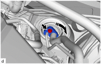

Remove in this Direction Remove the bolt and rotate the hook connector as shown in the illustration.
-
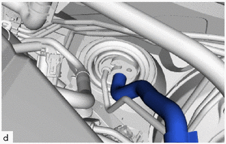
Disconnect the suction pipe sub-assembly.
-
Remove the O-ring from the suction pipe sub-assembly.
Note
Seal the openings of the disconnected parts using vinyl tape to prevent entry of moisture and foreign matter.
-
-
DISCONNECT COOLER REFRIGERANT LIQUID PIPE A
-
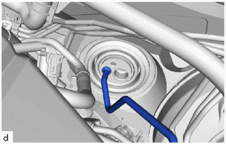
Disconnect the cooler refrigerant liquid pipe A.
-
Remove the O-ring from the cooler refrigerant liquid pipe A.
Note
Seal the openings of the disconnected parts using vinyl tape to prevent entry of moisture and foreign matter.
-
-
DISCONNECT OUTLET HEATER WATER HOSE
-
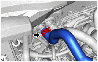
Slide the hose clip to disconnect the outlet heater water hose.
Note
-
To prevent contamination by foreign matter or water droplets, protect the connecting portions of the outlet heater water hose and air conditioner radiator assembly with plastic bags.
-
Do not apply excessive force to the outlet heater water hose.
-
Prepare a drain pan or cloth in case the coolant leaks.
-
-
-
DISCONNECT INLET HEATER WATER HOSE
-
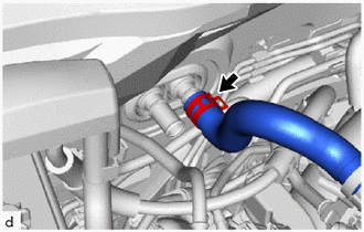
Slide the hose clip to disconnect the inlet heater water hose.
Note
-
To prevent contamination by foreign matter or water droplets, protect the connecting portions of the inlet heater water hose and air conditioner radiator assembly with plastic bags.
-
Do not apply excessive force to the inlet heater water hose.
-
Prepare a drain pan or cloth in case the coolant leaks.
-
-
-
REMOVE FRONT SEAT ASSEMBLY LH
-
REMOVE FRONT SEAT ASSEMBLY RH
Tech Tips
Use the same procedure as for the LH side.
-
REMOVE INSTRUMENT PANEL SAFETY PAD SUB-ASSEMBLY
-
REMOVE STEERING COLUMN ASSEMBLY
-
REMOVE NO. 2 AIR DUCT SUB-ASSEMBLY
-
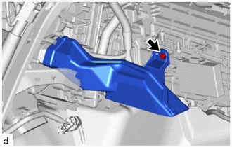
Remove the screw and No. 2 air duct sub-assembly.
-
-
REMOVE ROLL RATE AND VERTICAL ACCELERATION SENSOR (YAWRATE SENSOR)
-
REMOVE AIR CONDITIONING AMPLIFIER ASSEMBLY
-
REMOVE COOLER THERMISTOR
-
REMOVE ACCELERATOR PEDAL PAD
-
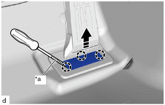
*a Protective Tape Remove in this Direction Using a screwdriver with its tip wrapped in protective tape, disengage the claws to remove the accelerator pedal pad as shown in the illustration.
-
-
REMOVE ACCELERATOR PEDAL
-
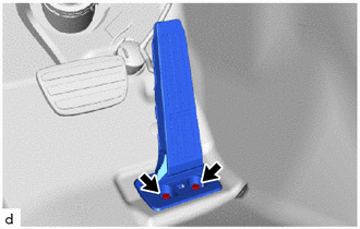
Remove the 2 bolts and accelerator pedal.
-
-
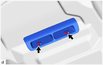
REMOVE AIR DUCT PLUG
-
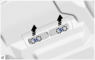
Remove in this Direction Disengage the claws to remove the air duct plug as shown in the illustration.
Tech Tips
Use the same procedure for both air duct plugs.
-
-
REMOVE REAR NO. 5 AIR DUCT
-
Remove the 2 screws and rear No. 5 air duct.
Tech Tips
Use the same procedure for both sides.
-
-
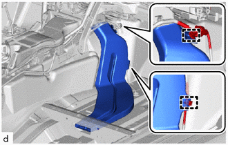
REMOVE REAR NO. 2 AIR DUCT
-
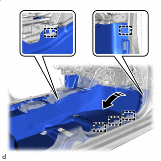
Disengage the claws.
-
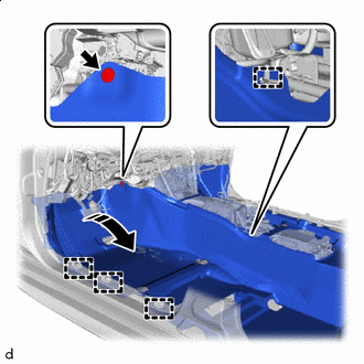
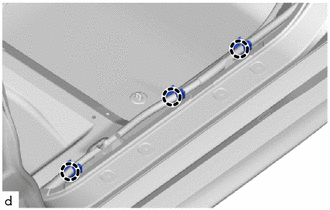
Remove in this Direction Using a clip remover, remove the clip.
-
Disengage the clamps to turn back the front floor carpet assembly as shown in the illustration.
-
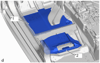
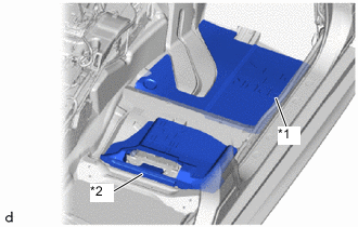
*1 Front Floor Silencer Pad LH *2 Center Floor Silencer Pad LH Remove the front floor silencer pad LH and center floor silencer pad LH.
-
Remove in this Direction Remove the nut.
-
Disengage the claws to remove the rear No. 2 air duct as shown in the illustration.
-
-
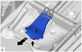
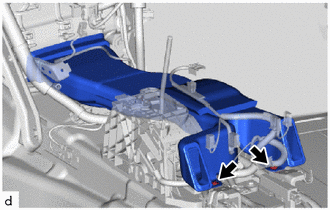
REMOVE REAR NO. 1 AIR DUCT
-
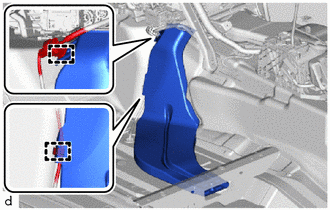
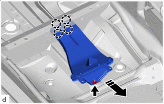
Disengage the clamps to disconnect the wire harness.
-
Remove the rear No. 1 air duct.
-
-
REMOVE REAR NO. 4 AIR DUCT
-
Disengage the claws.
-
Remove in this Direction Disengage the clamps.
-
Disengage the clamps to turn back the front floor carpet assembly as shown in the illustration.
-
*1 Front Floor Silencer Pad RH *2 Center Floor Silencer Pad RH Remove the front floor silencer pad RH and center floor silencer pad RH.
-
Remove in this Direction Remove the nut.
-
Disengage the claws to remove the rear No. 4 air duct as shown in the illustration.
-
-
REMOVE REAR NO. 3 AIR DUCT
-
Disengage the clamps to disconnect the wire harness.
-
Remove the rear No. 3 air duct.
-
-
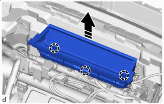
REMOVE NO. 1 CONSOLE BOX DUCT
-
Remove the 2 clips and No. 1 console box duct.
-
-
REMOVE NO. 1 AIR DUCT SUB-ASSEMBLY
-
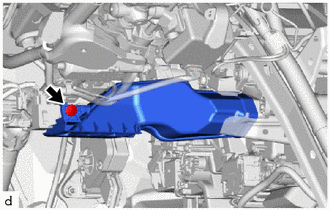
Remove the clip and No. 1 air duct sub-assembly.
-
-
REMOVE LOWER DEFROSTER NOZZLE ASSEMBLY
Remove in this Direction
-
Disengage the claws to remove the lower defroster nozzle assembly as shown in the illustration.
-
-
REMOVE AIR HOSE
-
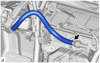
Remove the air hose.
-
-
REMOVE INSTRUMENT PANEL SAFETY PAD CAP
-
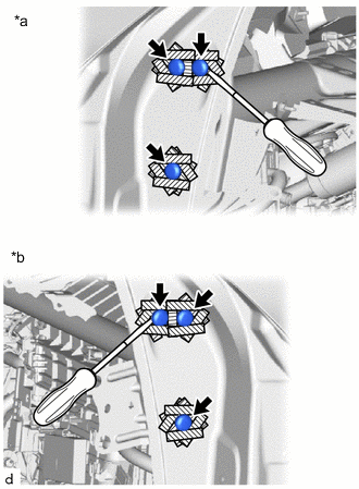
*a LH Side *b RH Side 
Protective Tape Apply protective tape around the 6 instrument panel safety pad caps.
-
Using a screwdriver, remove the 6 instrument panel safety pad caps.
-
-
REMOVE INSTRUMENT PANEL REINFORCEMENT ASSEMBLY WITH AIR CONDITIONING UNIT
Note
Be sure to support the air conditioning unit assembly when removing it because failure to do so may cause the bracket of the air conditioning unit assembly to break.
-
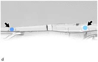
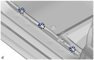
Remove the 2 grommets.
-
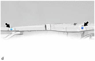
Remove the 2 bolts.
-
Remove the 4 bolts to disconnect the 4 ground wires.
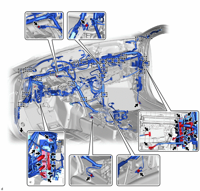
-
Disconnect the 15 connectors.
-
Disengage the clamps.
-
Remove the 2 bolts and 4 nuts to disconnect the instrument panel wire.
-
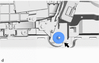
Remove the nut.
-
Remove the 9 bolts.
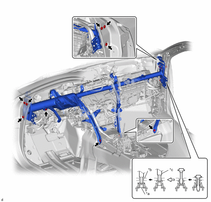
*a Collar *b Vehicle Body *c 12 mm Hexagon Wrench - - -
Using a 12 mm hexagon wrench, loosen the 3 collars as shown in the illustration.
-
Disengage the guides to remove the instrument panel reinforcement assembly with air conditioning unit as shown in the illustration.
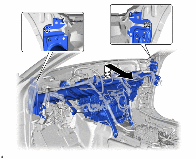
Remove in this Direction - - -
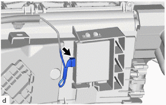
Disconnect the ID code box (immobiliser code ECU) connector.
-
-
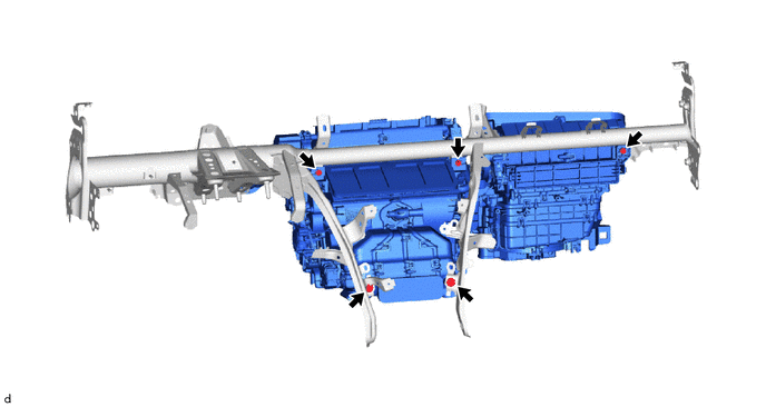
REMOVE AIR CONDITIONING UNIT
-
Remove the 2 screws, 3 bolts and air conditioning unit from the instrument panel reinforcement assembly.
-