NAVIGATION SYSTEM, Diagnostic DTC:B1532
| DTC Code | DTC Name |
|---|---|
| B1532 | LVDS Signal Malfunction (from Extension Module) |
DESCRIPTION
The navigation ECU and the radio and display receiver assembly are connected via LVDS communication line.
This DTC is stored when an LVDS communication error occurs between the navigation ECU and the radio and display receiver assembly.
| DTC No. | Detection Item | DTC Detection Condition | Trouble Area |
|---|---|---|---|
| B1532 | LVDS Signal Malfunction (from Extension Module) | When any of the following conditions is met:
|
|
Tech Tips
-
Even if no malfunction is present, this DTC may be stored depending on the auxiliary battery condition or hybrid control system start voltage.
-
The radio and display receiver assembly is the master unit.
WIRING DIAGRAM
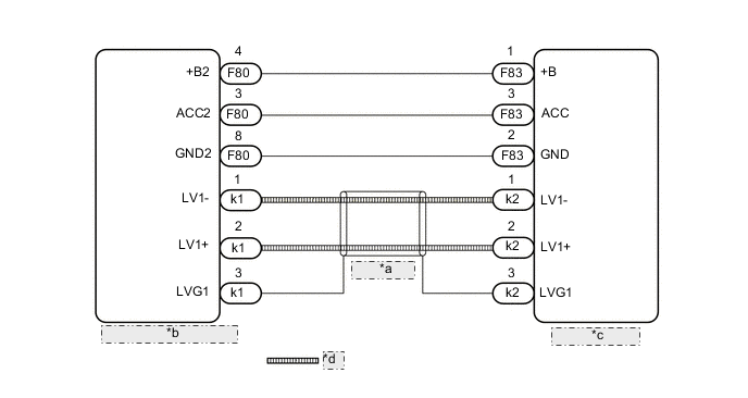
| *a | (Shielded) |
| *b | Radio and Display Receiver Assembly |
| *c | Navigation ECU |
| *d | LVDS Communication Line |
PROCEDURE
-
CHECK HARNESS AND CONNECTOR (NAVIGATION ECU POWER SOURCE)
-
Disconnect the F83 navigation ECU connector.
-
Measure the resistance according to the value(s) in the table below.
Standard Resistance Tester Connection Condition Specified Condition F83-2 (GND) - Body ground Always Below 1 Ω -
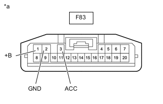
*a Front view of wire harness connector
(to Navigation ECU)
Measure the voltage according to the value(s) in the table below.
Standard Voltage Tester Connection Condition Specified Condition F83-1 (+B) - F83-2 (GND) Power switch off 11 to 14 V F83-3 (ACC) - F83-2 (GND) Power switch on (ACC) 11 to 14 V Result Proceed to OK NG
NG 
CHECK HARNESS AND CONNECTOR (RADIO AND DISPLAY RECEIVER ASSEMBLY - NAVIGATION ECU) Click here
OK 
-
-
REPLACE HARNESS AND CONNECTOR (LVDS COMMUNICATION LINE)
-
Replace the harness and connector (LVDS communication line) with a new or known good one.
-
Clear the DTCs.
Body Electrical > Navigation System > Clear DTCs -
Recheck for DTCs and check that no DTCs are output.
Body Electrical > Navigation System > Trouble CodesOK No DTCs are output. Result Proceed to OK NG
OK 
END
NG
-
-
REPLACE NAVIGATION ECU
-
Replace the navigation ECU with a new or known good one.
-
Clear the DTCs.
Body Electrical > Navigation System > Clear DTCs -
Recheck for DTCs and check that no DTCs are output.
Body Electrical > Navigation System > Trouble CodesOK No DTCs are output. Result Proceed to OK NG
OK
END
NG
REPLACE RADIO AND DISPLAY RECEIVER ASSEMBLY Click here
-
-
CHECK HARNESS AND CONNECTOR (RADIO AND DISPLAY RECEIVER ASSEMBLY - NAVIGATION ECU)
-
Disconnect the F80 radio and display receiver assembly connector.
-
Disconnect the F83 navigation ECU connector.
-
Measure the resistance according to the value(s) in the table below.
Standard Resistance Tester Connection Condition Specified Condition F80-4 (+B2) - F83-1 (+B) Always Below 1 Ω F80-3 (ACC2) - F83-3 (ACC) Always Below 1 Ω F80-8 (GND2) - F83-2 (GND) Always Below 1 Ω F80-4 (+B2) - Body ground Always 10 kΩ or higher F80-3 (ACC2) - Body ground Always 10 kΩ or higher F80-8 (GND2) - Body ground Always 10 kΩ or higher Result Proceed to OK NG
OK
REPLACE RADIO AND DISPLAY RECEIVER ASSEMBLY Click here
NG
REPAIR OR REPLACE HARNESS OR CONNECTOR
-