AIRBAG SYSTEM, Diagnostic DTC:B1800/51, B1801/51, B1802/51, B1803/51

| DTC Code | DTC Name |
|---|---|
| B1800/51 | Short in Driver Side Squib Circuit |
| B1801/51 | Open in Driver Side Squib Circuit |
| B1802/51 | Short to GND in Driver Side Squib Circuit |
| B1803/51 | Short to B+ in Driver Side Squib Circuit |
DESCRIPTION
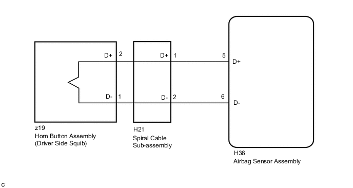
The driver side squib circuit consists of the airbag sensor assembly, spiral cable sub-assembly and horn button assembly.
The airbag sensor assembly uses this circuit to deploy the airbag when deployment conditions are met.
These DTCs are stored when a malfunction is detected in the driver side squib circuit.
| DTC No. | DTC Detection Condition | Trouble Area |
|---|---|---|
| B1800/51 |
|
|
| B1801/51 |
|
|
| B1802/51 |
|
|
| B1803/51 |
|
WIRING DIAGRAM
CAUTION / NOTICE / HINT
Note
After turning the engine switch off, waiting time may be required before disconnecting the cable from the negative (-) battery terminal. Therefore, make sure to read the disconnecting the cable from the negative (-) battery terminal notices before proceeding with work Click here.
Tech Tips
-
Perform the simulation method by selecting check mode (Signal Check) using the GTS Click here.
-
After selecting check mode (Signal Check), perform the simulation method by wiggling each connector of the airbag system or driving the vehicle on a city road or rough road Click here.
PROCEDURE
-
CHECK CONNECTORS
-
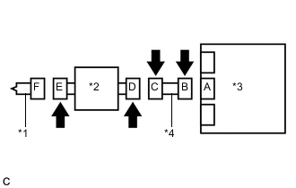
Text in Illustration *1 Horn Button Assembly *2 Spiral Cable Sub-assembly *3 Airbag Sensor Assembly *4 Instrument Panel Wire Turn the engine switch off.
-
Disconnect the cable from the negative (-) battery terminal.
CAUTION:
Wait at least 90 seconds after disconnecting the cable from the negative (-) battery terminal to disable the SRS system.
-
Check that the connectors are properly connected to the horn button assembly, spiral cable sub-assembly and airbag sensor assembly.
OK The connectors are properly connected. Tech Tips
If the connectors are not connected securely, reconnect the connectors and proceed to the next inspection.
-
Disconnect the connectors from the horn button assembly, spiral cable sub-assembly and airbag sensor assembly.
-
Check that the terminals of the connectors are not damaged.
OK The terminals are not deformed or damaged. -
Check that the spiral cable sub-assembly connector (on the horn button assembly side) is not damaged.
OK The lock button is not disengaged, or the claw of the lock is not deformed or damaged. -
Check that the short springs for the instrument panel wire and spiral cable sub-assembly with the activation prevention mechanism are not deformed or damaged.
OK The short springs are not deformed or damaged.
NG 
REPLACE WIRE HARNESS
OK 
-
-
CHECK HORN BUTTON ASSEMBLY (DRIVER SIDE SQUIB)
-
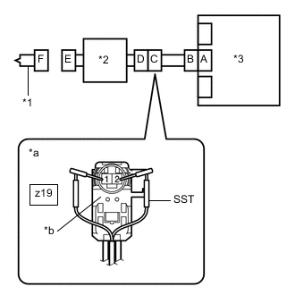
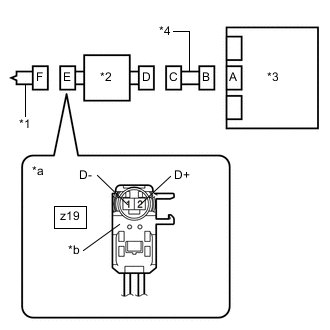
*1 Horn Button Assembly *2 Spiral Cable Sub-assembly *3 Airbag Sensor Assembly *a Front view of wire harness connector
(to Horn Button Assembly)
*b Color: Light Green Connect the instrument panel wire to the airbag sensor assembly and spiral cable sub-assembly.
-
Connect SST (resistance 2.1 Ω) to connector E (light green connector).
CAUTION:
Never connect the tester to the horn button assembly (driver side squib) for measurement, as this may lead to a serious injury due to airbag deployment.
Note
-
Do not forcibly insert SST into the terminals of the connector when connecting it.
-
Insert SST straight into the terminals of the connector.
- SST
- 09843-18061
-
-
Connect the cable to the negative (-) battery terminal.
-
Clear the DTCs stored in memory Click here.
-
Turn the engine switch off.
-
Turn the engine switch on (IG), and wait for at least 60 seconds.
-
Check for DTCs Click here.
OK DTC B1800/51, B1801/51, B1802/51 or B1803/51 is not output. Tech Tips
Codes other than DTCs B1800/51, B1801/51, B1802/51 and B1803/51 may be output at this time, but they are not related to this check.
-
Turn the engine switch off.
-
Disconnect the cable from the negative (-) battery terminal.
CAUTION:
Wait at least 90 seconds after disconnecting the cable from the negative (-) battery terminal to disable the SRS system.
-
Disconnect SST from connector E.
OK
REPLACE HORN BUTTON ASSEMBLY Click here
NG
-
-
CHECK DRIVER SIDE SQUIB CIRCUIT
-
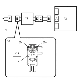
*1 Horn Button Assembly *2 Spiral Cable Sub-assembly *3 Airbag Sensor Assembly *a Front view of wire harness connector
(to Horn Button Assembly)
*b Color: Light Green Disconnect the instrument panel wire from the airbag sensor assembly.
-
Check for a short to B+ in the circuit.
-
Connect the cable to the negative (-) battery terminal.
-
Turn the engine switch on (IG).
-
Measure the voltage according to the value(s) in the table below.
Standard Voltage Tester Connection Condition Specified Condition z19-2 (D+) - Body ground Engine switch on (IG) Below 1 V z19-1 (D-) - Body ground Engine switch on (IG) Below 1 V -
Turn the engine switch off.
-
Disconnect the cable from the negative (-) battery terminal.
CAUTION:
Wait at least 90 seconds after disconnecting the cable from the negative (-) battery terminal to disable the SRS system.
-
-
Check for an open in the circuit.
-
Measure the resistance according to the value(s) in the table below.
Standard Resistance Tester Connection Condition Specified Condition z19-2 (D+) - z19-1 (D-) Always Below 1 Ω
-
-
Check for a short to ground in the circuit.
-
Measure the resistance according to the value(s) in the table below.
Standard Resistance Tester Connection Condition Specified Condition z19-2 (D+) - Body ground Always 1 MΩ or higher z19-1 (D-) - Body ground Always 1 MΩ or higher
-
-
Check for a short in the circuit.
-
Release the activation prevention mechanism built into connector B Click here.
-
Measure the resistance according to the value(s) in the table below.
Standard Resistance Tester Connection Condition Specified Condition z19-2 (D+) - z19-1 (D-) Always 1 MΩ or higher -
Restore the released activation prevention mechanism of connector B to the original condition.
-
NG 
CHECK INSTRUMENT PANEL WIRE Click here
OK
-
-
CHECK DTC
-
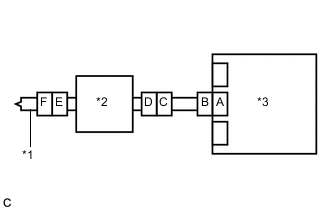
Text in Illustration *1 Horn Button Assembly *2 Spiral Cable Sub-assembly *3 Airbag Sensor Assembly Connect the connectors to the horn button assembly and airbag sensor assembly.
-
Connect the cable to the negative (-) battery terminal.
-
Clear the DTCs stored in memory Click here.
-
Turn the engine switch off.
-
Turn the engine switch on (IG), and wait for at least 60 seconds.
-
Check for DTCs Click here.
OK DTC B1800/51, B1801/51, B1802/51 or B1803/51 is not output. Tech Tips
Codes other than DTCs B1800/51, B1801/51, B1802/51 and B1803/51 may be output at this time, but they are not related to this check.
OK
USE SIMULATION METHOD TO CHECK Click here
NG
REPLACE AIRBAG SENSOR ASSEMBLY Click here
-
-
CHECK INSTRUMENT PANEL WIRE
-
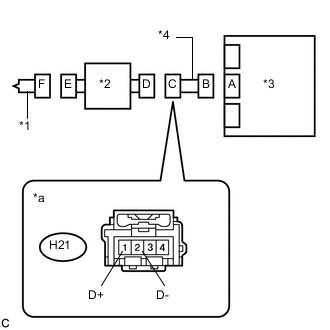
Text in Illustration *1 Horn Button Assembly *2 Spiral Cable Sub-assembly *3 Airbag Sensor Assembly *4 Instrument Panel Wire *a Front view of wire harness connector
(to Spiral Cable Sub-assembly)
Disconnect the instrument panel wire from the spiral cable sub-assembly.
-
Check for a short to B+ in the circuit.
-
Connect the cable to the negative (-) battery terminal.
-
Turn the engine switch on (IG).
-
Measure the voltage according to the value(s) in the table below.
Standard Voltage Tester Connection Condition Specified Condition H21-1 (D+) - Body ground Engine switch on (IG) Below 1 V H21-2 (D-) - Body ground Engine switch on (IG) Below 1 V -
Turn the engine switch off.
-
Disconnect the cable from the negative (-) battery terminal.
CAUTION:
Wait at least 90 seconds after disconnecting the cable from the negative (-) battery terminal to disable the SRS system.
-
-
Check for an open in the circuit.
-
Measure the resistance according to the value(s) in the table below.
Standard Resistance Tester Connection Condition Specified Condition H21-1 (D+) - H21-2 (D-) Always Below 1 Ω
-
-
Check for a short to ground in the circuit.
-
Measure the resistance according to the value(s) in the table below.
Standard Resistance Tester Connection Condition Specified Condition H21-1 (D+) - Body ground Always 1 MΩ or higher H21-2 (D-) - Body ground Always 1 MΩ or higher
-
-
Check for a short in the circuit.
-
Release the activation prevention mechanism built into connector B Click here.
-
Measure the resistance according to the value(s) in the table below.
Standard Resistance Tester Connection Condition Specified Condition H21-1 (D+) - H21-2 (D-) Always 1 MΩ or higher -
Restore the released activation prevention mechanism of connector B to the original condition.
-
NG
REPLACE INSTRUMENT PANEL WIRE
OK
-
-
CHECK SPIRAL CABLE SUB-ASSEMBLY
-
*1 Horn Button Assembly *2 Spiral Cable Sub-assembly *3 Airbag Sensor Assembly *4 Instrument Panel Wire *a Front view of wire harness connector
(to Horn Button Assembly)
*b Color: Light Green Check for a short to B+ in the circuit.
-
Connect the cable to the negative (-) battery terminal.
-
Turn the engine switch on (IG).
-
Measure the voltage according to the value(s) in the table below.
Standard Voltage Tester Connection Condition Specified Condition z19-2 (D+) - Body ground Engine switch on (IG) Below 1 V z19-1 (D-) - Body ground Engine switch on (IG) Below 1 V -
Turn the engine switch off.
-
Disconnect the cable from the negative (-) battery terminal.
CAUTION:
Wait at least 90 seconds after disconnecting the cable from the negative (-) battery terminal to disable the SRS system.
-
-
Check for an open in the circuit.
-
Measure the resistance according to the value(s) in the table below.
Standard Resistance Tester Connection Condition Specified Condition z19-2 (D+) - z19-1 (D-) Always Below 1 Ω
-
-
Check for a short to ground in the circuit.
-
Measure the resistance according to the value(s) in the table below.
Standard Resistance Tester Connection Condition Specified Condition z19-2 (D+) - Body ground Always 1 MΩ or higher z19-1 (D-) - Body ground Always 1 MΩ or higher
-
-
Check for a short in the circuit.
-
Release the activation prevention mechanism built into connector D Click here.
-
Measure the resistance according to the value(s) in the table below.
Standard Resistance Tester Connection Condition Specified Condition z19-2 (D+) - z19-1 (D-) Always 1 MΩ or higher -
Restore the released activation prevention mechanism of connector D to the original condition.
-
OK
USE SIMULATION METHOD TO CHECK Click here
NG
REPLACE SPIRAL CABLE SUB-ASSEMBLY Click here
-