VEHICLE STABILITY CONTROL SYSTEM, Diagnostic DTC:C1241

| DTC Code | DTC Name |
|---|---|
| C1241 | Low Power Supply Voltage Malfunction |
DESCRIPTION
If a malfunction is detected in the power supply circuit, the skid control ECU (brake actuator assembly) stores this DTC and the fail-safe function prohibits ABS operation.
This DTC is stored when the +BS terminal voltage deviates from the DTC detection condition due to a malfunction in the power supply or charging circuit such as the battery or generater circuit, etc.
The DTC is canceled when the +BS terminal voltage returns to normal.
| DTC No. | DTC Detection Condition | Trouble Area |
|---|---|---|
| C1241 | Any of the following is detected:
|
|
WIRING DIAGRAM
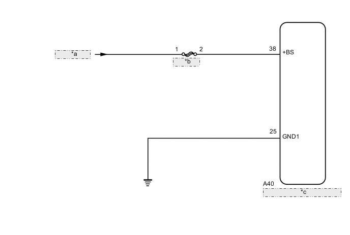
| *a | from Battery |
| *b | ABS NO. 2 |
| *c | Skid Control ECU (Brake Actuator Assembly) |
CAUTION / NOTICE / HINT
Note
-
When replacing the skid control ECU (brake actuator assembly), perform zero point calibration and store system information Click here.
-
Inspect the fuses for circuits related to this system before performing the following inspection procedure.
PROCEDURE
-
INSPECT BATTERY
-
Check the battery voltage.
Standard Voltage 11 to 14 V Result Result Proceed to OK A NG (for 2AR-FE) B NG (for 2GR-FE) C NG (for 6AR-FSE) D
B 
CHECK OR REPLACE CHARGING SYSTEM OR BATTERY Click here
C
CHECK OR REPLACE CHARGING SYSTEM OR BATTERY Click here
D
CHECK OR REPLACE CHARGING SYSTEM OR BATTERY Click here
A 
-
-
CHECK HARNESS AND CONNECTOR (+BS TERMINAL)
-
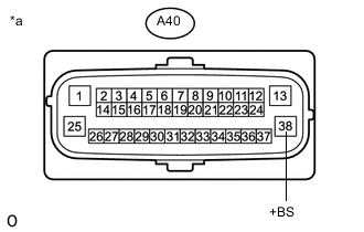
Text in Illustration *a Front view of wire harness connector
(to Skid Control ECU (Brake Actuator Assembly))
Make sure that there is no looseness at the locking part and connecting part of the connectors.
-
Disconnect the A40 skid control ECU (brake actuator assembly) connector.
-
Turn the engine switch on (IG).
-
Measure the voltage according to the value(s) in the table below.
Standard Voltage Tester Connection Condition Specified Condition A40-38 (+BS) - Body ground Engine switch on (IG) 11 to 14 V
NG
REPAIR OR REPLACE HARNESS OR CONNECTOR (+BS CIRCUIT)
OK
-
-
CHECK HARNESS AND CONNECTOR (GND1 TERMINAL)
-
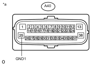
Text in Illustration *a Front view of wire harness connector
(to Skid Control ECU (Brake Actuator Assembly))
Turn the engine switch off.
-
Measure the resistance according to the value(s) in the table below.
Standard Resistance Tester Connection Condition Specified Condition A40-25 (GND1) - Body ground Always Below 1 Ω
NG
REPAIR OR REPLACE HARNESS OR CONNECTOR (GND1 CIRCUIT)
OK
-
-
RECONFIRM DTC
-
Reconnect the A40 skid control ECU (brake actuator assembly) connector.
-
Clear the DTCs Click here.
-
Turn the engine switch off.
-
Start the engine.
-
Drive the vehicle at a speed of 20 km/h (12 mph) or more for 30 seconds or more.
-
Check if the same DTC is output Click here.
Result Result Proceed to DTC C1241 is not output. A DTC C1241 is output. B Tech Tips
If troubleshooting has been carried out according to Problem Symptoms Table, refer back to the table and proceed to the next step before replacing parts Click here.
A
USE SIMULATION METHOD TO CHECK Click here
B
REPLACE BRAKE ACTUATOR ASSEMBLY Click here
-